Virtual Shadow Map In XEngine
Introduction
Virtual Shadow Maps (VSMs) is the new shadow mapping method used in Unreal Engine 5. I implemented a simplified virtual shadow maps in my personal game engine. Here is a brief introduction from the official unreal engine 5 documentation:
Virtual Shadow Maps have been developed with the following goals:
- Significantly increase shadow resolution to match highly detailed Nanite geometry
- Plausible soft shadows with reasonable, controllable performance costs
- Provide a simple solution that works by default with limited amounts of adjustment needed
- Replace the many Stationary Light shadowing techniques with a single, unified path
Conceptually, virtual shadow maps are just very high-resolution shadow maps. In their current implementation, they have a virtual resolution of 16k x 16k pixels. Clipmaps are used to increase resolution further for Directional Lights. To keep performance high at reasonable memory cost, VSMs split the >shadow map into tiles (or Pages) that are 128x128 each. Pages are allocated and rendered only as needed to shade on-screen pixels based on an analysis of the depth buffer. The pages are cached between frames unless they are invalidated by moving objects or light, which further improves performance.
We have implemented the four features described in the Unreal Engine VSM documentation, virtual high-resolution texture, clipmaps, only shading on-screen pixels and page caching, in our simplified virtual shadow map project. Here is the low-level architecture of our simplified VSMs:
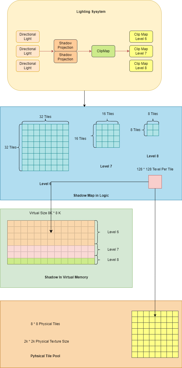
In XEngine’s simplified virtual shadow map, each directional light has a clip map with 3 levels: clip map level 6, clip map level 7 and clip map level 8. In addition, the maximum clip map level consists of 8 x 8 tiles, with the next clip map level having twice the number of tiles as the previous clip map level. The total tile number is 1344 (32 x 32 + 16 x 16 + 8 x 8), corresponding 8K x 8K virtual texture size. Each tile has 256 x 256 pixels in physical size and the physical tile pool has 2K by 2K pixels in physical size.
Overview
Note: For achieving the highest possible performance, it is recommended that combining the virtual shadow map with a Nanite-like technique dividing the mesh into clusters. Otherwise, fine-grained tile splitting could lead to a significant increase in draw calls and mesh face numbers by drawing meshes across different tiles repeatedly. Nanite’s spliting mesh into clusters makes the mesh size smaller, decreasing the probability that the drawing units, clusters or the whole mesh, cross more than one tile.
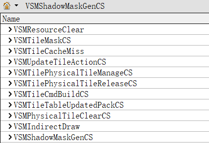
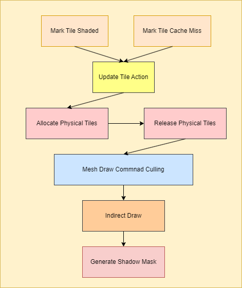
Simplified VSMs classify the tiles into different states, including shaded, not visible, cache missing and newly added, based on the scene depth and the mesh bound box. For each tile, different actions are performed based on its state, such as updating the physical tile content, allocating or removing the tile. After that, cull and build the mesh draw command for those tiles needed to be updated in the current frame. Finally, dispatch a set of indirect draw commands and compute the shadow mask using the shadow depth map rendered by indirect draw:
Mark Tile State
Mark Tiles Used
Only are the tiles contaning the objects recieving the shadow in the camera view space processed by the simplified virtual shadow map. In order to achieve this goal, VSMs analyze the scene depth buffer by convert the pixels from camera projection space to shadow view space to find which tile this pixel corresponds to. Moreover, VSMs calculate the clip map level this pixel belongs to based on its distance from the world space location to the camera’s. As shown in the following image, the green blocks are marked as active tiles in VSMs, while the red blocks are not active.
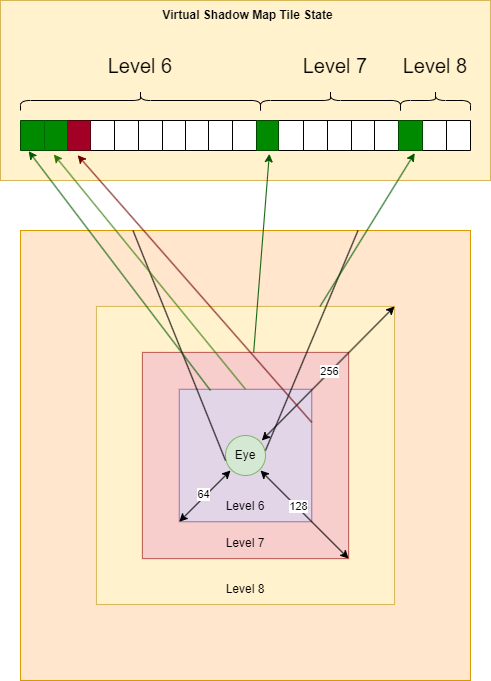
Simplified VSMs have 3 clip map levels, whose ranges are 2^(6 + 1) ,2^(7 + 1) and 2^(8 + 1). The first level is 6, meaning that pixels whose distance to the camera ranges from 0 to 2^6 are belong to this level. Based on the mip level, shadow space UV, and mip size, we can determine which tile this pixel belongs to.
1 | |
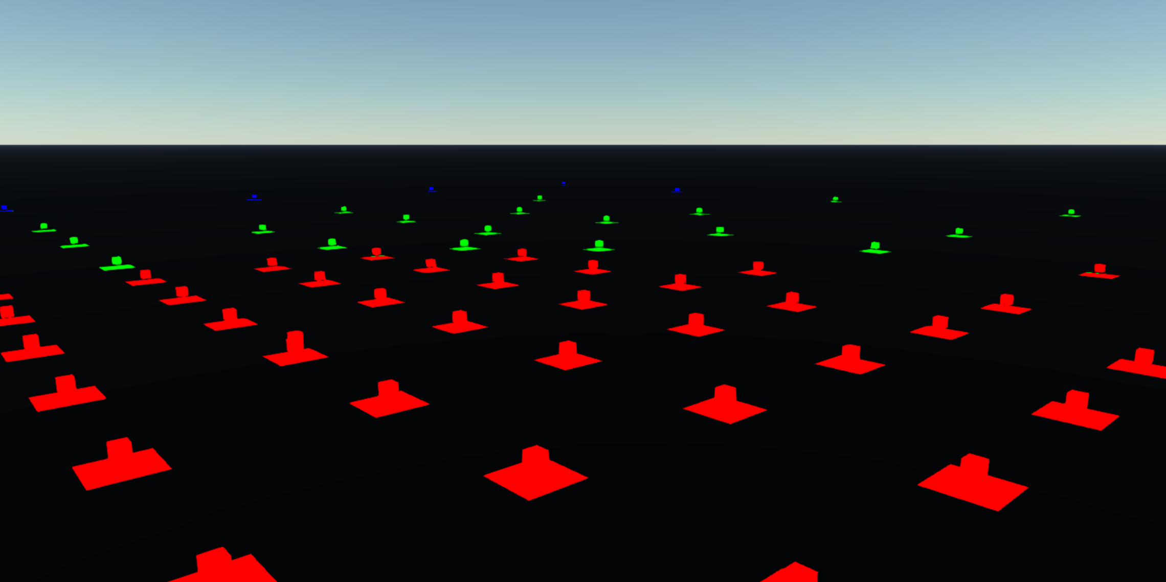
Here is a visualization of the mip level for the scene. The Mip Levels 6 / 7 / 8 correspond to the colors red, green, and blue, respectively.
Mark Cache Miss Tiles
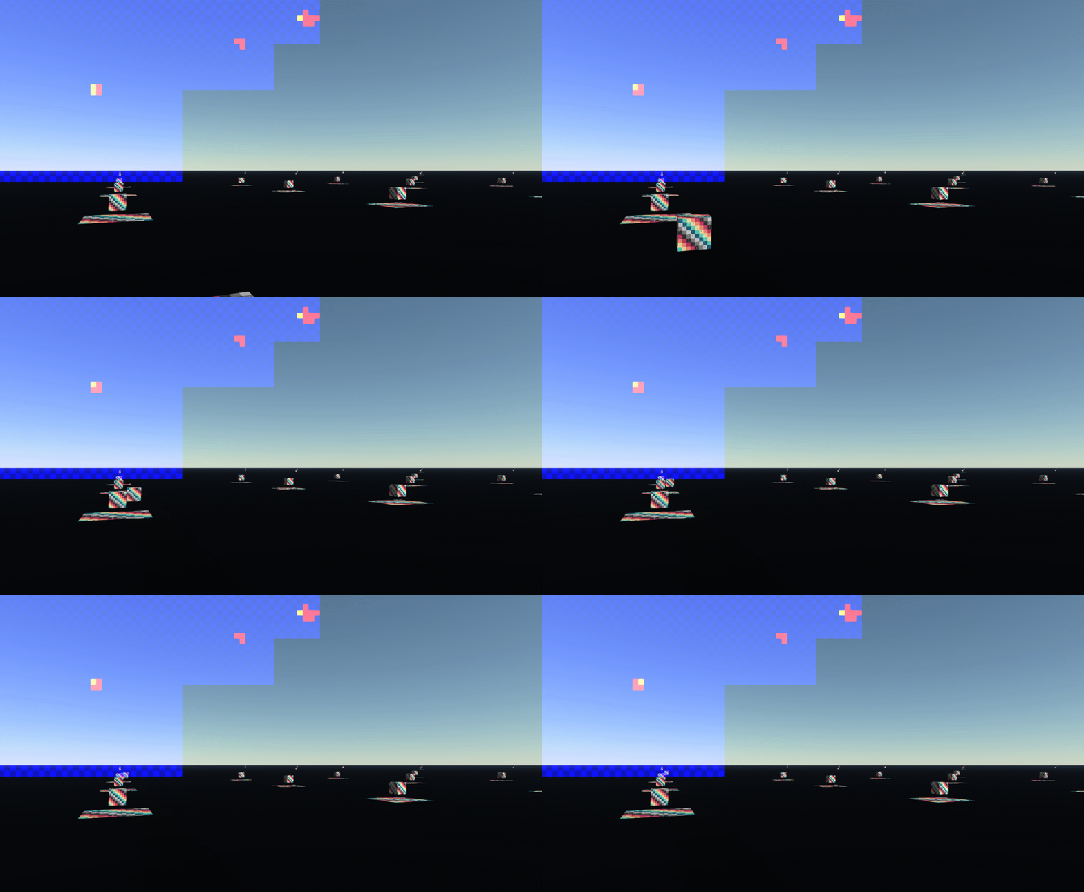
Update only the tiles having changed compared to the previous frame, which reduces the number of draw calls by reusing the previous frame data cached in the virtual shadow map texture. For finding all of the tiles that changed in the current frame, simplified VSMs project the bound boxes of the dynamic objects receiving shadow into the shadow view space. Following that, the tiles rendered in the current frame as well as within these bound boxes’ projected area are iterated and marked as cache missing. All tiles’ mip levels covered are conservatively marked as cache misses. The following gif image shows the cache missing tile with yellow color updated every frame:
Update Tile Action
During the tile action updating pass, VSMs firstly compare the current state with the last frame’s state using a ping-pong buffer storing the previous tile table buffer, containing the indices to the physical tile texture, and the previous tile state buffer.
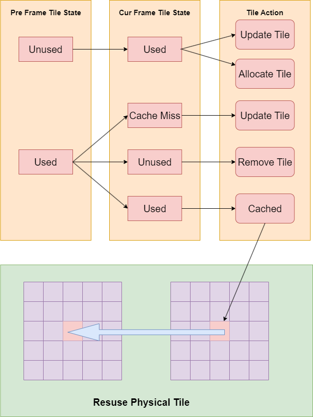
Current frame’s newly added tiles will allocate a new physical tile and update the shadow rendering content. Cached tiles, reused by being assigned with the index copied from the corresponding position in the last frame’s tile table, only update the shadow rendering, which is no need to allocate an extra physical tile.
1 | |
Physical Tile Management
The physical tile manager, maintaining a list of available physical tiles and an extra counter buffer recording the available list header node, allocates a free tile from the free tile list when the tile action equals TILE_ACTION_NEED_ALLOCATE and assigns the tile index to the corresponding position of the current frame virtual tile table when the tile action equals TILE_ACTION_NEED_ALLOCATE. What’s more, the physical tile manager will obtain the released tile index from the previous frame tile table and push it to the back of the free tile list if the tile action is TILE_ACTION_NEED_REMOVE.
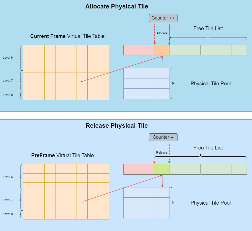
The tile release and allocate action, performed in seperate compute passes, moves the counter forward or backward by the InterlockedAdd instruction. We release the tile buffer immediately for simplicity after the tiles are marked as TILE_ACTION_NEED_REMOVE, while UE5’s VSMs maintains a LRU list in the physical tile manager removing the tile when requested by the new tile actually .
1 | |
1 | |
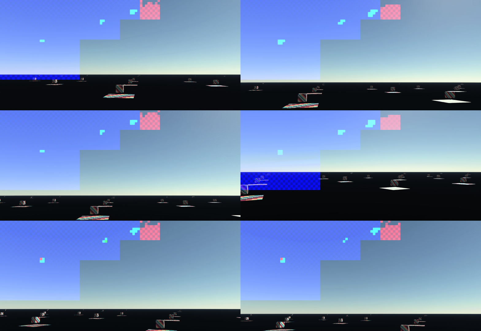
Rotating the camera, the free tiles, red blocks in the top-right corner, are changed, as shown in the following gif:
Cull And Build The Shadow Draw Command
Allocate The Shadow Commands
VSMs build the command on the GPU and render the shadow map by indirect draw command. Here is the indirect command layout specified on the application side: constant buffer view for per-object transform information, tile info cbv, vertex buffer view, index buffer view and indirect argument desc.
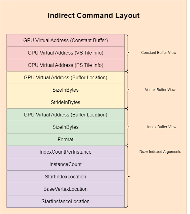
After that, on the application side, the command data, containing the GPU address of the buffer, information about the vertex/index buffer and information associated with the object mesh, is allocated. In the final step, initialize the scene command buffer with the data allocated above and create an empty culled command buffer, a collection of commands used in shadow map rendering after GPU culling, with the same size as the scene command buffer.
1 | |
Build Indirect Shadow Command
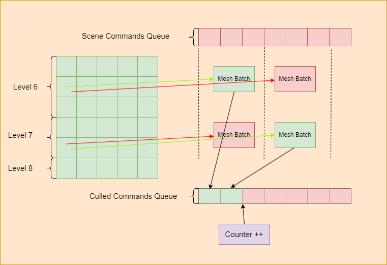
For each tile, we dispatch 50 threads to process the mesh batch, each of whom has 1 / 50 of the total mesh draw commands. Simplified VSMs cull the mesh draw commands based on the shadow space area of the mesh bound box after projection. When the meshes are not culled by the tile frustum, its corresponding commands are pushed to the output command queue by InterLockedAdd.
GPU “Pointer”
Creating a bridge between the indirect draw command and the virtual shadow map is critical for obtaining the tile information. UE5 VSM’s solution, using InstanceID to index the virtual tile table, requires recording an extra InstanceOffset variable for each mesh, since the StartInstanceLocation cannot be obtained from the vertex shader if the shading language is beyond SM 6.8. In Simplified VSMs, we use “GPU Pointer” to point the GPU address of the tile information buffer.
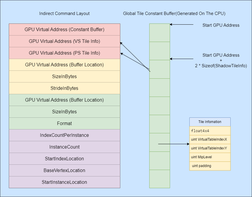
Simplified VSM generates the information including a view-proj matrix, mip leve and tile indexes on the GPU side for each tile. The GPU address of each tile with the tile is calculated with the tile index and the base GPU address that recorded on the application side. Since the GPU pointer is 64 bits and HLSL doesn’t support 64 bits integer addition, we implement a custom 64 bit addition for the GPU pointer:
1 | |
The tile’s GPU address is simply the addition of the tile offset and the base address.
1 | |
Shadow Map Rendering
All pre-requirements having been met, shadow map rendering is easy to implement by dispatching an indirect draw pass followed by clearing the physical tiles requiring updating.
1 | |
The destination pixel written position is determined by calculating the MIP level based on the world position and calculating the virtual table index based on the GPU pointer.
1 | |
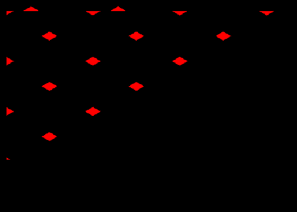
Here is the visualization of the physical shadow depth texture:

Generate The Shadow Mask Texture
By calculating the virtual table index from the pixel position, calculating the physical shadow depth position from the table index, and comparing the result to the pixel’s shadow space depth, we can finally determine whether this pixel is shadowed.
1 | |
1 | |
