Simplified Nanite In MiniEngine

Overview

This is a simplified Nanite implementation (SimNanite) based on Unreal’s Nanite virtual geometry. We have implemented most of Unreal Nanite’s features.

In offline, we partition the triangles into clusters with the Metis graph partition library. Then, SimNanite partitions the clusters into cluster groups, builds the DAG (Directed Acyclic Graph) and BVH tree based on the cluster groups. In order to avoid the LOD crack, SimNanite simplify the mesh globally rather than simplifying the triangles per cluster.

At runtime, we implement a three-level GPU culling pipeline: instance culling, BVH node culling and cluster culling. In the BVH node culling pass, we use the MPMC ( Multiple Producers, Single Consumer ) model to transverse the BVH structure and integrate the cluster culling into the BVH culling shader for work balance.

We generate an indirect draw or indirect dispatch command for those clusters that pass the culling. If the cluster is small enough, we employ the software rasterization with compute shader.

During the rasterization pass, we write the cluster index and triangle index to the visibility buffer. In the next base pass or GBuffer rendering, we fetch these indices from the visibility buffer, calculate the pixel attributes (UV and normal) by barycentric coordinates and render the scene with these attributes.

Nanite Builder

Overview

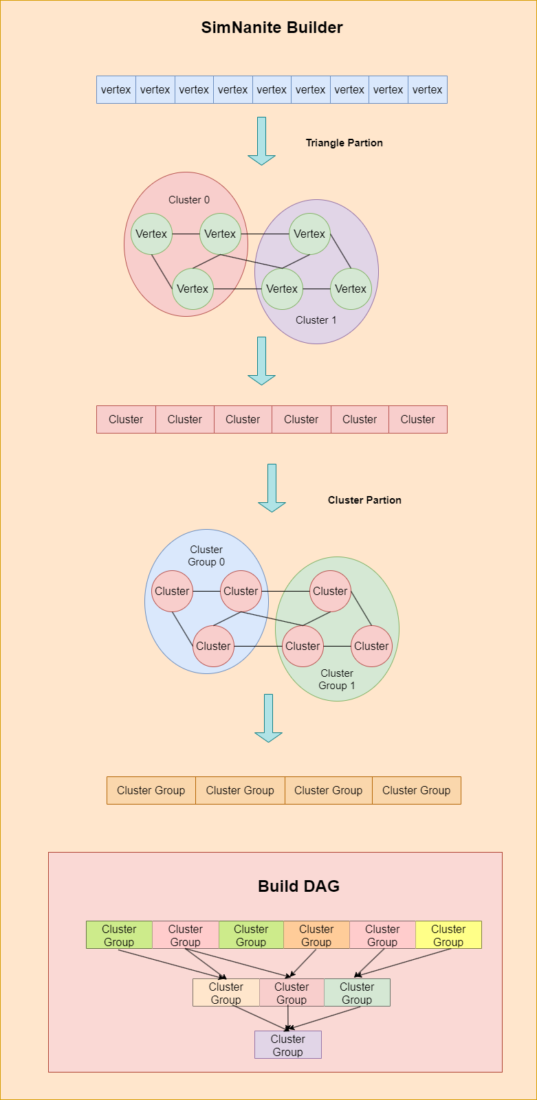
SimNanite (Simplified Nanite) building is an offline mesh processing during mesh import. It splits the mesh into clusters to provide a fine-grained mesh culling with a graph partition algorithm. Beyond the cluster level, SimNanite partitions the cluster into groups to accelerate mesh culling. Cluster groups are the leaf nodes of the BVH structure. In addtion, SimNanite simplifies the merged clusters at the current level rather than separate clusters in order to avoid the Lod crack artifact without boundnary edge locking.
Triangle Partition

SimNanite partitions the mesh into clusters in order to perform fine-grained GPU culling. Meshes can be viewed as graphs, whose nodes are vertex points and edges are mesh topology. With the graph representation, we can partition it with the Metis graph library.

Given a mesh without an index buffer, SimNanite processes the mesh triangles sequentially. For each triangle, SimNanite hash the vertex position to find the vertex index of the adjacent list array. Each vertex in the triangle has 6 edges. We add these edge points into the coresponding vertex adjacent unordered_set.
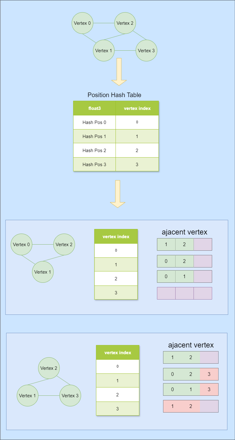
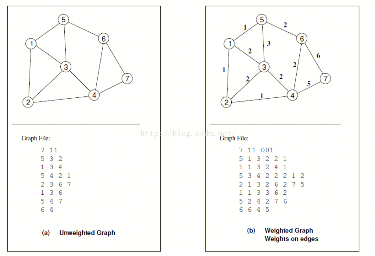
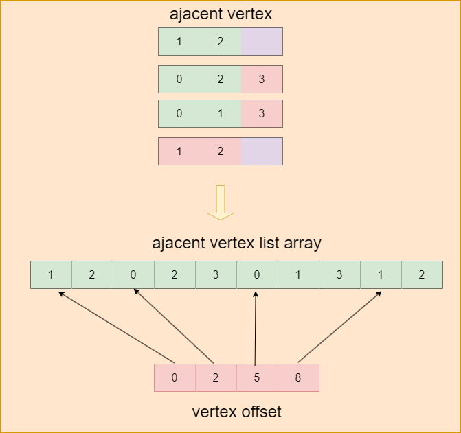
The Metis library’s graph partition function input has two parts: vertex adjacent list array and vertex adjacent offsets. Vertex adjacent offsets record the offsets of each vertex in the vertex adjacent list.
With the adjacent vertex list for each vertex, we can pack them into an array and record their offsets.
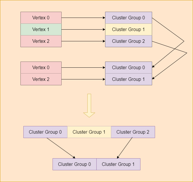
After the triangle partition, Metis outputs an array containing the partition index of each vertex. The next step is to batch the triangles into clusters with the partition result and find out the linked clusters for each cluster. If the vertices of one triangle belong to different partitions, this triangle can be viewed as an “edge-cluster”. We add these clusters to the linked clusters array in order to partition the clusters in the next step.

1
2
3
4
5
6
7
8
9
10
11
12
13
14
15
16
17
18
19
20
21
22
23
24
25
26
27
28
29
30
31
32
idx_t tri_parts[3];
tri_parts[0] = part_a;

int triangle_part_num = 1;
if (part_b != part_a)
{
tri_parts[triangle_part_num] = part_b;
triangle_part_num++;
}

if ((part_c != part_a) && (part_c != part_b))
{
tri_parts[triangle_part_num] = part_c;
triangle_part_num++;
}

if (triangle_part_num == 2)
{
out_clusters[tri_parts[0]].m_linked_cluster.insert(tri_parts[1]);
out_clusters[tri_parts[1]].m_linked_cluster.insert(tri_parts[0]);
}
else if (triangle_part_num == 3)
{
out_clusters[tri_parts[0]].m_linked_cluster.insert(tri_parts[1]);
out_clusters[tri_parts[0]].m_linked_cluster.insert(tri_parts[2]);

out_clusters[tri_parts[1]].m_linked_cluster.insert(tri_parts[0]);
out_clusters[tri_parts[1]].m_linked_cluster.insert(tri_parts[2]);

out_clusters[tri_parts[2]].m_linked_cluster.insert(tri_parts[0]);
out_clusters[tri_parts[2]].m_linked_cluster.insert(tri_parts[1]);
}

Cluster Partition

With clusters and linked clusters, we can partition them into cluster groups as we do in the triangle partition pass. Cluster group is the leaf node in BVH acceleration structure. Usually, it consists of four to eight clusters.
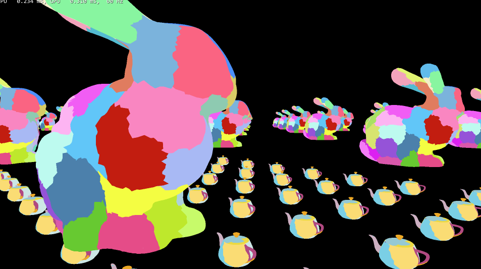
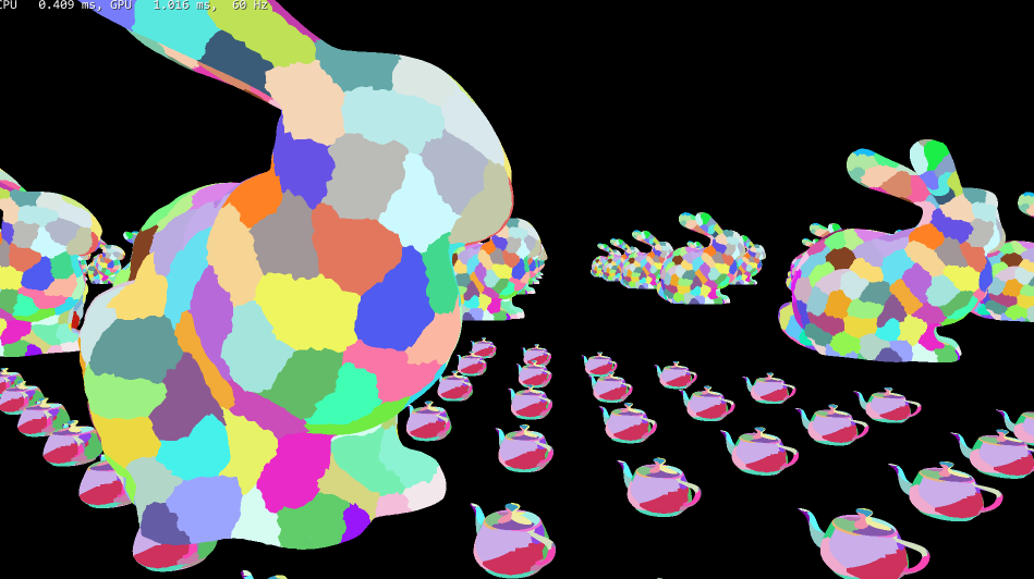
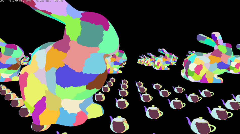
Below is the cluster visualization at LOD level 0, 1 and 2 in SimNanite:
Mesh Simplification

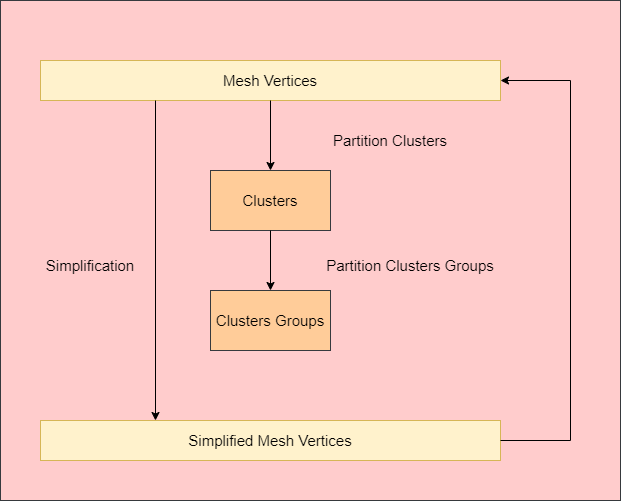
We simplify the mesh until the cluster number is less than 24 or fails to simplify the mesh. The mesh simplification library is Meshoptimizer. It employs the QEM method to simplify the mesh, which is similar to what the Unreal Engine does. Another important point is that we simplify the global mesh rather than the cluster, as the latter method causes the LOD crack whitout boundnary edge locking.
Build DAG

In the DAG (Directed Acyclic Graph) building pass, we organize the data and translate it into a GPU-friendly structure to acclerate to GPU-culling performed later.
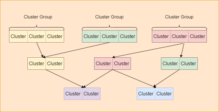
SimNanite merges the resources of all lod level into a global resource array. That is to say, a simnanite mesh resource only has one vertex buffer, one index buffer, one cluster group array and one cluster array. UE’s Nanite performs an additional compression process after mesh building. We ignore compression for simplicity.
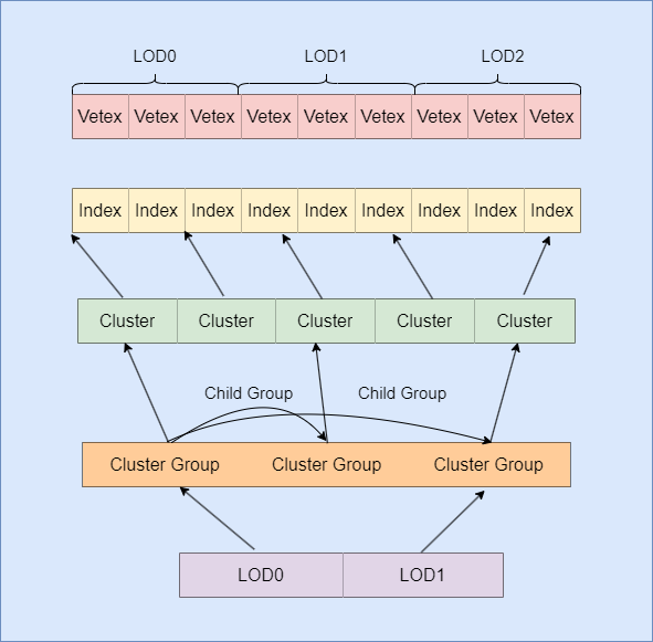
A nanite mesh resource contains several lod resources. Each LOD resource stores cluster group indices in the current level. The max cluster group number per LOD is 8. It stores the vertex and index location in the mesh vertex buffer. Nanite mesh building consume a lot of time. To accelerate programming efficiency, we serialize the DAG structure on the disk and load it without building at the next launch.

1
2
3
4
5
6
7
8
9
10
11
12
13
14
15
16
17
18
19
20
21
22
23
24
25
26
27
28
29
30
31
32
33
34
35
36
37
38
39
40
41
42
43
44
45
46
47
struct CSimNaniteClusterResource
{
DirectX::BoundingBox m_bouding_box;

int m_index_count;
int m_start_index_location;
int m_start_vertex_location;
};

struct CSimNaniteClusterGrpupResource
{
DirectX::BoundingBox m_bouding_box;
float cluster_next_lod_dist;
int m_child_group_num;
int m_cluster_num;

std::vector<int>m_child_group_indices;
std::vector<int>m_clusters_indices;

typedef void (*group_serialize_fun)(char*, long long, void* streaming);
void Serialize(group_serialize_fun func, void* streaming);
};

struct CSimNaniteLodResource
{
int m_cluster_group_num;
int m_cluster_group_index[8];
};

class CSimNaniteMeshResource
{
public:
SSimNaniteMeshHeader m_header;

DirectX::BoundingBox m_bouding_box;

std::vector<DirectX::XMFLOAT3> m_positions;
std::vector<DirectX::XMFLOAT3> m_normals;
std::vector<DirectX::XMFLOAT2> m_uvs;
std::vector<unsigned int> m_indices;

std::vector<CSimNaniteClusterGrpupResource> m_cluster_groups;
std::vector<CSimNaniteClusterResource>m_clusters;
std::vector<CSimNaniteLodResource> m_nanite_lods;

void LoadFrom(const std::string& source_file_an, const std::wstring& source_file, bool bforce_rebuild = false);
};

Build BVH

UE’s nanite use BVH to acclerate the GPU cluster group culling and LOD selection. In the offline, UE builds the BVH by SAH (Surface Area Heuristic) method. In SimNanite, we find the maximum dimension of the bound box extents and sort the cluster goups based on the position distribution in the maximum dimension. After that, we split the cluster groups into 4 nodes and build the whole BVH tree bottom-up. Each LOD has a root BVH node. For example, the mesh that has four LOD contains four root nodes.

1
2
3
4
5
6
7
8
9
10
11
12
13
14
15
16
17
18
19
20
21
22
23
24
25
26
std::vector<SClusterGroupBVHNode> leaf_nodes;
for (uint32_t clu_grp_idx = 0; clu_grp_idx < lod_resource.m_cluster_group_num; clu_grp_idx++)
{
uint32_t global_clu_grp_idx = lod_resource.m_cluster_group_start + clu_grp_idx;
SClusterGroupBVHNode leaf_node;
leaf_node.m_is_leaf_node = true;
leaf_node.m_cluster_group_index = global_clu_grp_idx;
leaf_node.m_bouding_box = out_nanite_reousource.m_cluster_groups[global_clu_grp_idx].m_bouding_box;
leaf_nodes.push_back(leaf_node);
}

uint32_t max_dimension_index = (bbox.Extents.x > bbox.Extents.y) ? 0 : 1;
float max_dimension = (bbox.Extents.x > bbox.Extents.y) ? bbox.Extents.x : bbox.Extents.y;
max_dimension_index = (max_dimension > bbox.Extents.z) ? max_dimension_index : 2;
max_dimension = (max_dimension > bbox.Extents.z) ? max_dimension : bbox.Extents.z;
SCustomLess custom_less;
custom_less.m_split_dimension = max_dimension_index;

std::sort(leaf_nodes.begin(), leaf_nodes.end(), custom_less);

uint32_t offset = bvh_nodes.size();
uint32_t level_node_num = leaf_nodes.size();
for (uint32_t leaf_idx = 0; leaf_idx < leaf_nodes.size(); leaf_idx++)
{
bvh_nodes.push_back(leaf_nodes[leaf_idx]);
}

Culling

Instance Culling

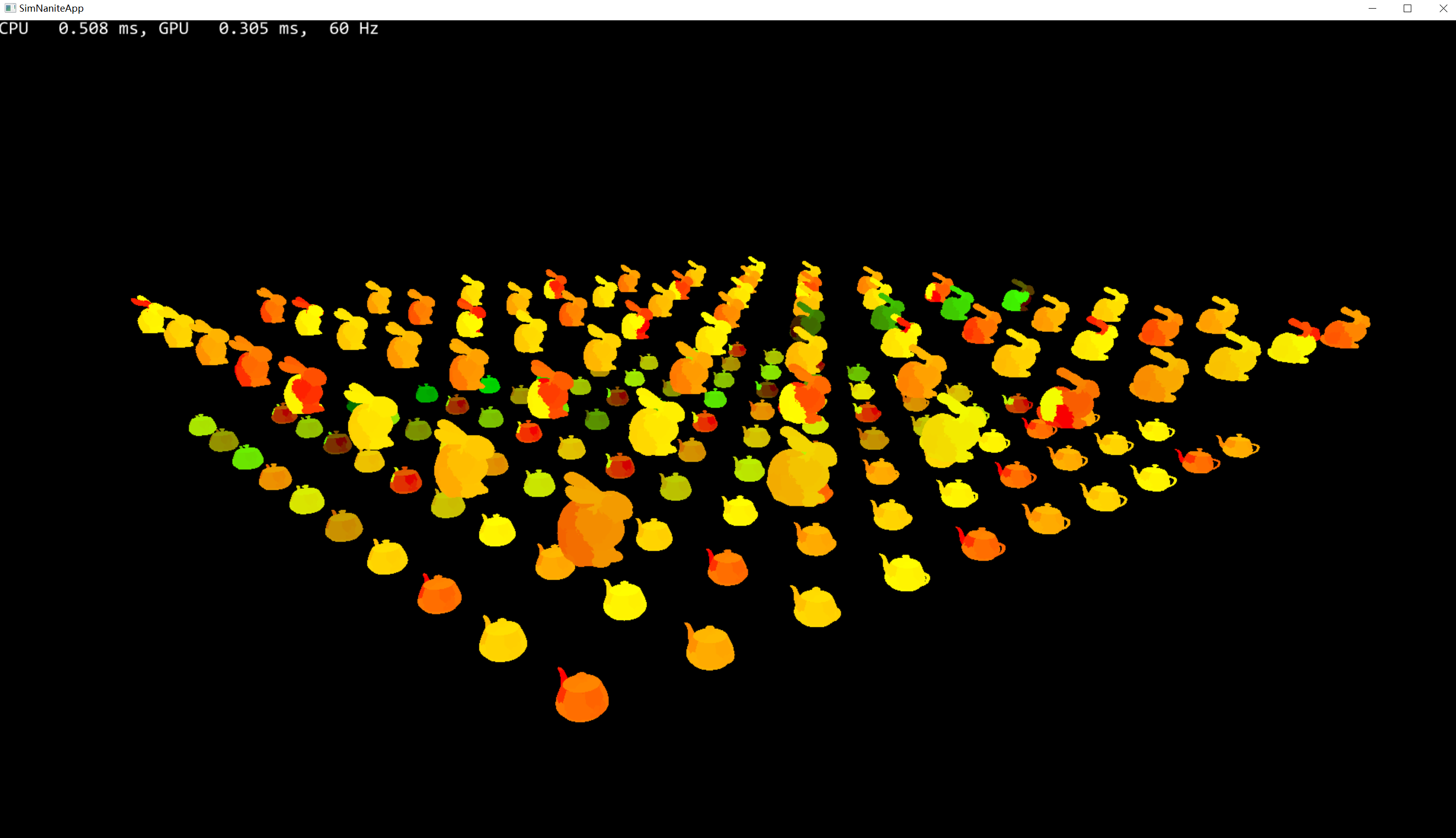
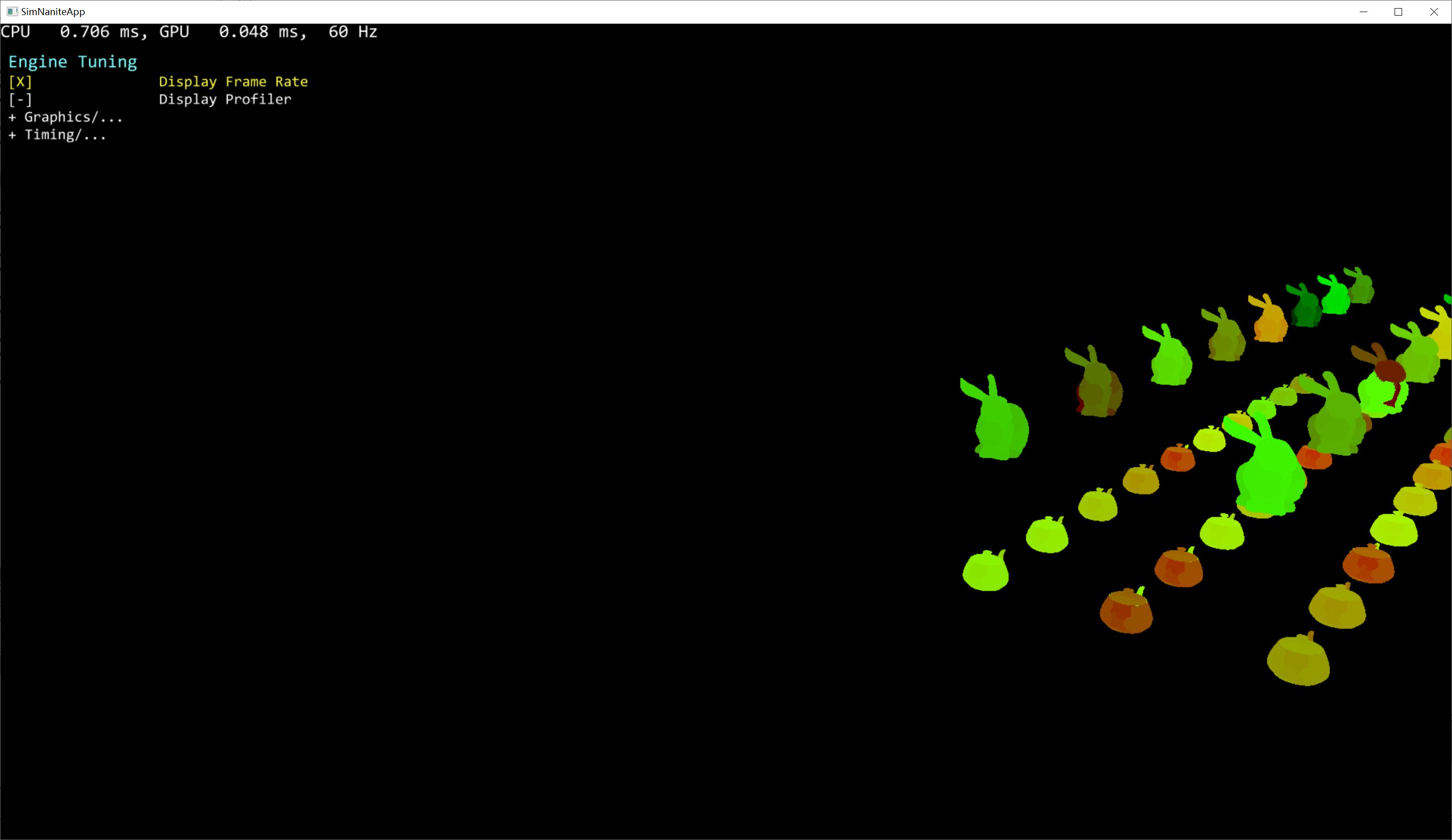
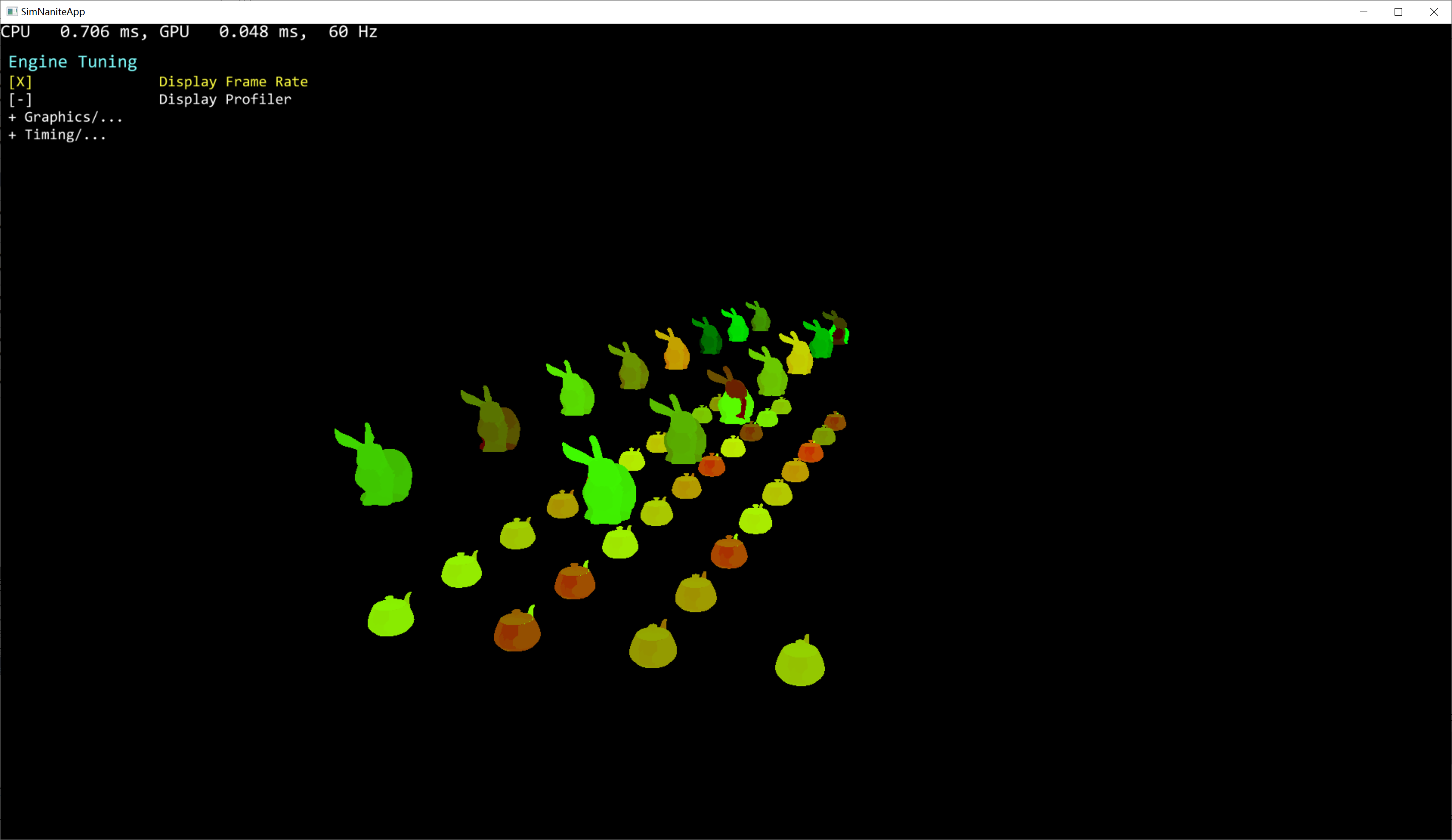
This step performs instance-level GPU-Culling, which is easy to implement and not necessary to detail it. The input of this step is the scene instance data and the output is the instance culled by the camera.

scene instance data:
instances viewed by camera:
instances culled by camera:
Persistent Culling

I tried to implement a DAG transversal at first. But I found it was too complicated to traverse to DAG in the compute shader. So I finally use the BVH structure to traverse the cluster group on GPU, which is same as the unreal does.

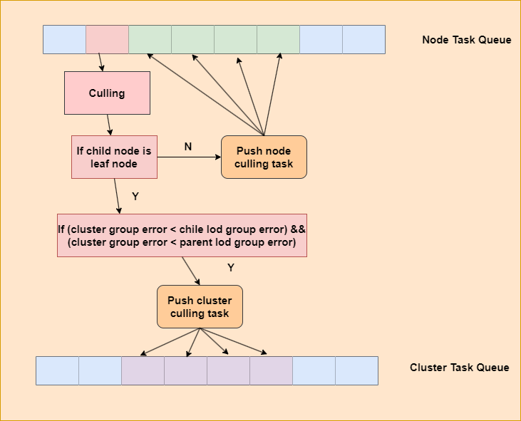
UE’s Nanite use the MPMC ( Multiple Producers, Single Consumer ) model to transverse the BVH structure. What’s more, it integrates the cluster culling into BVH culling shader for work balance. In SimNanite, we have implemented the two features (MPMC and integrate cluster culling) mentioned above.
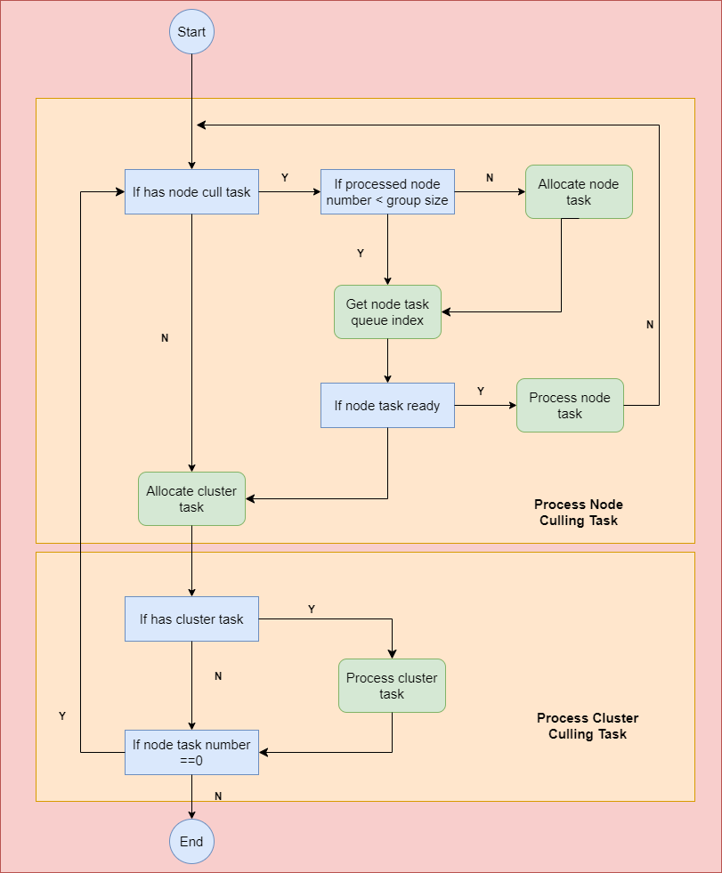
SimNanite processes the node culling tasks at first. After the previous node culling task has completed, the first thread in the group fetches the node tasks from the node MPMC culling task queue.

1
2
3
4
5
6
7
8
9
10
11
if(node_processed_size == GROUP_PROCESS_NODE_NUM)
{
if(group_index == 0)
{
InterlockedAdd(queue_pass_state[0].node_task_read_offset, GROUP_PROCESS_NODE_NUM, group_start_node_idx);
}
GroupMemoryBarrierWithGroupSync();

node_processed_size = 0;
node_start_idx = group_start_node_idx;
}

Then, the compute group counts the node tasks ready to process.

1
2
3
4
5
if(is_node_ready)
{
InterlockedOr(group_node_processed_mask, 1u << group_index);
}
AllMemoryBarrierWithGroupSync();

We start the node culling task when at least one node is ready in the group. SimNanite generates cluster culling tasks and pushes these tasks to the cluster culling queue if a node is a leaf node and its cluster group error is small enough. Otherwise, SimNanite generates BVH node culling tasks and push these to the BVH node culling queue.
Cluster Culling

Cluster culling is a two-pass process. The first pass is performed at the persistent culling stage. It will process the cluster culling task if there are no node culling tasks for the compute group to process. SimNanite dispatches an additional cluster culling pass after the persistent culling stage to process tasks that were not handled in the previous stage.

1
2
3
4
5
6
7
8
9
10
11
12
13
14
15
16
17
18
19
20
21
22
23
24
25
26
27
28
29
30
31
32
33
34
35
36
37
38
39
40
if(clu_task_start_index == 0xFFFFFFFFu)
{
if(group_index == 0)
{
InterlockedAdd(queue_pass_state[0].cluster_task_read_offset, 1, group_start_clu_index);
}
GroupMemoryBarrierWithGroupSync();
clu_task_start_index = group_start_clu_index;
}

if (group_index == 0)
{
group_node_task_num = queue_pass_state[0].node_num;
group_clu_task_size = cluster_task_batch_size.Load(clu_task_start_index * 4 /*sizeof uint*/);
}
GroupMemoryBarrierWithGroupSync();

uint clu_task_ready_size = group_clu_task_size;
if(!has_node_task && clu_task_ready_size == 0)
{
break;
}

if(clu_task_ready_size > 0)
{
if(group_index < clu_task_ready_size)
{
const uint2 cluster_task = cluster_task_queue.Load2(clu_task_start_index * 8 /*sizeof(uint2)*/);
const uint cluster_task_instance_index = cluster_task.x;
const uint cluster_task_clu_start_index = cluster_task.y;
ProcessCluster(cluster_task_instance_index, cluster_task_clu_start_index + group_index);
}
clu_task_start_index = 0xFFFFFFFFu;
}

int node_task_num = group_node_task_num;
if (has_node_task && node_task_num == 0)
{
has_node_task = false;
}

Generate Indirect Draw Command

An indirect draw command is generated during cluster culling. SimNanite uses software rasterization for those clusters that are small enough, which is the same as UE’s Nanite solution.
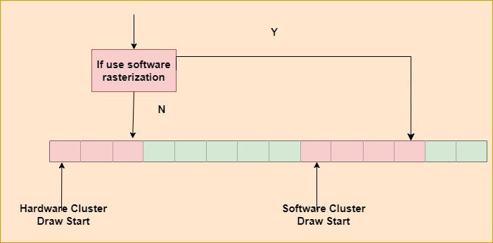
SimNanite uses instance ID to index the cluster buffer for hardware rasterization. For software rasterization, SimNanite uses group ID to index the cluster buffer. Each compute group processes one cluster triangle.

1
2
3
4
5
6
7
8
9
10
11
12
SIndirectDrawParameters indirect_draw_parameters;
indirect_draw_parameters.vertex_count = 1701;
indirect_draw_parameters.instance_count = hardware_indirect_draw_num.Load(0);
indirect_draw_parameters.start_vertex_location = 0;
indirect_draw_parameters.start_instance_location = 0;
hardware_draw_indirect[0] = indirect_draw_parameters;

SIndirectDispatchCmd indirect_dispatch_parameters;
indirect_dispatch_parameters.thread_group_count_x = software_indirect_draw_num.Load(0);
indirect_dispatch_parameters.thread_group_count_y = 1;
indirect_dispatch_parameters.thread_group_count_z = 1;
software_draw_indirect[0] = indirect_dispatch_parameters;

Hardware Rasterization

SimNanite uses indirect draw instances for hardware rasterization clusters. Vertex shaders index clusters by instance ID. Clusters store the information about the vertex buffer range. It should be noticed that all vertex buffers in the scene are merged into a global single buffer. Otherwise, we can rasterize the scene only with an indirect draw call if we don’t merge buffers together. UE’s Nanite also implement a complicated steaming solution for the global scene vertex buffer mannagement.
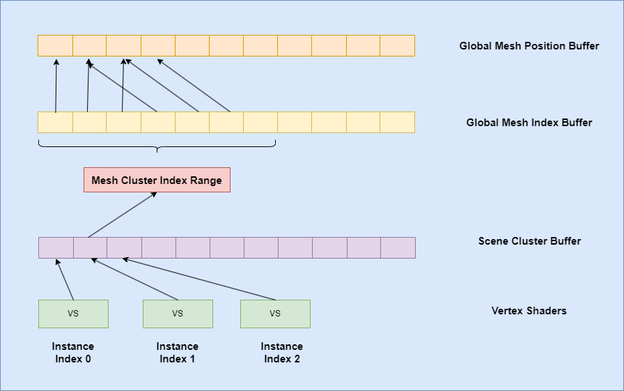
We load the vertex position data indexed by scene index buffer and culled from cluster buffer. After MVP transform, we store the cluster index and triangle index into the visibility buffer. In additional, we store the material index to the material ID buffer, which will be used as depth test buffer in the latter rendering pass.

1
2
3
4
5
6
7
8
9
10
11
12
13
14
15
16
17
18
19
if(vertex_id < index_count)
{
uint index_read_pos = start_index_location + vertex_id;

uint vertex_index_idx = global_index_buffer.Load(index_read_pos * 4/*sizeof int*/);
uint vertex_idx = vertex_index_idx + start_vertex_location;

float3 vertex_position = asfloat(global_vertex_pos_buffer.Load3((vertex_idx * 3)* 4/*sizeof int*/));

uint triangle_id = vertex_id / 3;
uint visibility_value = triangle_id & 0x0000FFFFu;
visibility_value = visibility_value | uint(instance_id << 16u);

float4 position = float4(vertex_position, 1.0);
float3 worldPos = mul(cluster_draw.world_matrix, position).xyz;
vsOutput.position = mul(ViewProjMatrix, float4(worldPos, 1.0));
vsOutput.visibility_value = visibility_value;
vsOutput.material_idx = cluster_draw.material_idx;
}

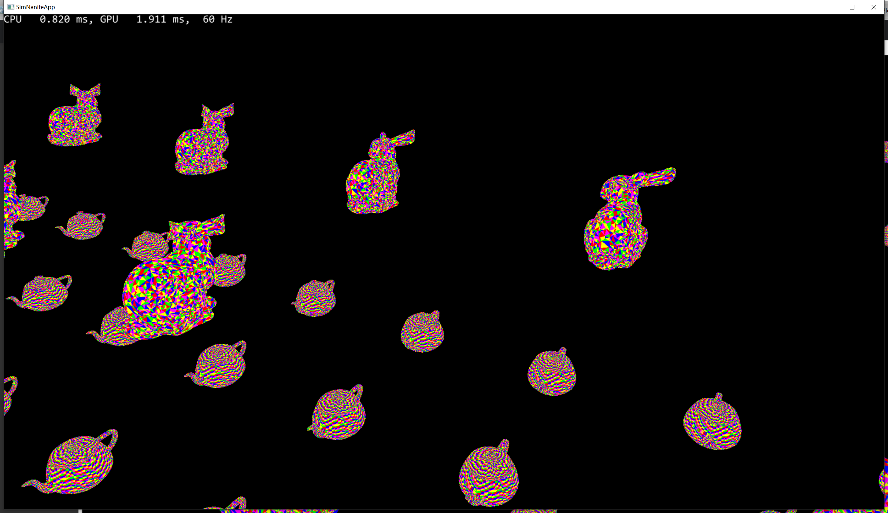
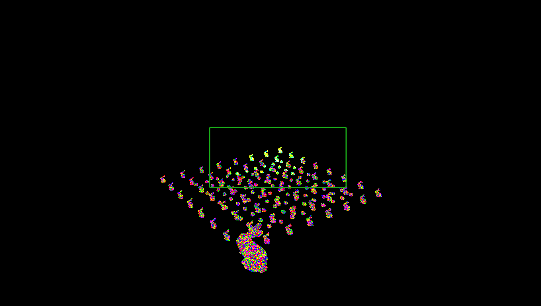
Bellow is the visibility buffer visualization:
Software Rasterization

In cases of triangles that are small enough, we use software rasterization by the compute shader. Each thread in the compute group processes one triangle. First, load the vertex position buffer based on the triangle index and the cluster index.

1
2
3
4
5
6
uint start_index_this_triangle = start_index_location + triangle_index * 3;
uint3 indices = global_index_buffer.Load3((start_index_this_triangle / 3) * 3 * 4 /* 3 * sizeof(uint) */);

float3 vertex_pos_a = asfloat(global_vertex_pos_buffer.Load3((start_vertex_location + indices.x) * 3 * 4 /* 3 * sizeof(float)*/));
float3 vertex_pos_b = asfloat(global_vertex_pos_buffer.Load3((start_vertex_location + indices.y) * 3 * 4 /* 3 * sizeof(float)*/));
float3 vertex_pos_c = asfloat(global_vertex_pos_buffer.Load3((start_vertex_location + indices.z) * 3 * 4 /* 3 * sizeof(float)*/));

Then, calculate the screen position based on the cluster instance world matrix and view projection matrix.

1
2
3
4
5
6
7
8
9
10
11
12
13
14
15
16
17
float4x4 world_matrix = cluster_draw.world_matrix;

float4 worldPos_a = mul(world_matrix, position_a).xyzw;
float4 worldPos_b = mul(world_matrix, position_b).xyzw;
float4 worldPos_c = mul(world_matrix, position_c).xyzw;

float4 clip_pos_a = mul(ViewProjMatrix, worldPos_a);
float4 clip_pos_b = mul(ViewProjMatrix, worldPos_b);
float4 clip_pos_c = mul(ViewProjMatrix, worldPos_c);

float3 ndc_pos_a = float3(clip_pos_a.xyz / clip_pos_a.w);
float3 ndc_pos_b = float3(clip_pos_b.xyz / clip_pos_b.w);
float3 ndc_pos_c = float3(clip_pos_c.xyz / clip_pos_c.w);

float4 screen_pos_a = float4((ndc_pos_a.x + 1.0f) * 0.5f * rendertarget_size.x, (ndc_pos_a.y + 1.0f) * 0.5f * rendertarget_size.y, ndc_pos_a.z, clip_pos_a.w);
float4 screen_pos_b = float4((ndc_pos_b.x + 1.0f) * 0.5f * rendertarget_size.x, (ndc_pos_b.y + 1.0f) * 0.5f * rendertarget_size.y, ndc_pos_b.z, clip_pos_b.w);
float4 screen_pos_c = float4((ndc_pos_c.x + 1.0f) * 0.5f * rendertarget_size.x, (ndc_pos_c.y + 1.0f) * 0.5f * rendertarget_size.y, ndc_pos_c.z, clip_pos_c.w);

Execute the back face culling process.

1
2
3
4
if(IsBackFace(ndc_pos_a, ndc_pos_b, ndc_pos_c))
{
return;
}

Rasterize the screen pixels covered by triangles. This is the simplest implementation and can be optimized in the future.

1
2
3
4
5
6
7
8
9
10
11
12
13
int2 bbox_min = (int2)min(screen_pos_a.xy,  min(screen_pos_b.xy, screen_pos_c.xy));
int2 bbox_max = (int2)max(screen_pos_a.xy, max(screen_pos_b.xy, screen_pos_c.xy));

if(bbox_max.x > 0 && bbox_max.y > 0 && bbox_min.x < rendertarget_size.x && bbox_min.y < rendertarget_size.y)
{
for (int y = bbox_min.y; y <= bbox_max.y; y++)
{
for (int x = bbox_min.x; x <= bbox_max.x; x++)
{
......
}
}
}

Finally, we calculate the barycentric coordinates and screen depth of this pixel. The compute shader is not able to perform a hardware depth test, so we convert the depth value type from float to int and use InterlockedMax to perform a software depth test.

1
2
3
4
5
6
7
8
9
10
11
12
13
14
15
16
17
18
19
20
float3 barycentric = BarycentricCoordinate(float2(x, y), screen_pos_a.xy, screen_pos_b.xy, screen_pos_c.xy);
if(barycentric.x >= 0 && barycentric.y >= 0 && barycentric.z >= 0)
{
float depth = barycentric.x * screen_pos_a.z + barycentric.y * screen_pos_b.z + barycentric.z * screen_pos_c.z;

uint depth_uint = depth * 0x7FFFFFFFu;
uint2 pixel_pos = uint2(x, rendertarget_size.y - y);
uint pre_depth;
InterlockedMax(intermediate_depth_buffer[pixel_pos], depth_uint, pre_depth);
if (depth_uint > pre_depth)
{
uint triangle_id = triangle_index;
uint visibility_value = triangle_id & 0x0000FFFFu;
visibility_value = visibility_value | uint(instance_id << 16u);

out_vis_buffer[pixel_pos] = visibility_value;
out_mat_id_buffer[pixel_pos] = cluster_draw.material_idx;
visualize_softrasterization[pixel_pos] = 1;
}
}

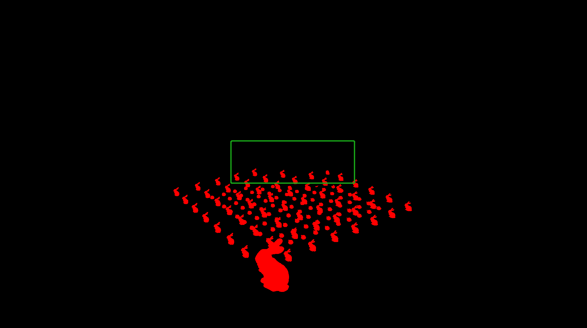
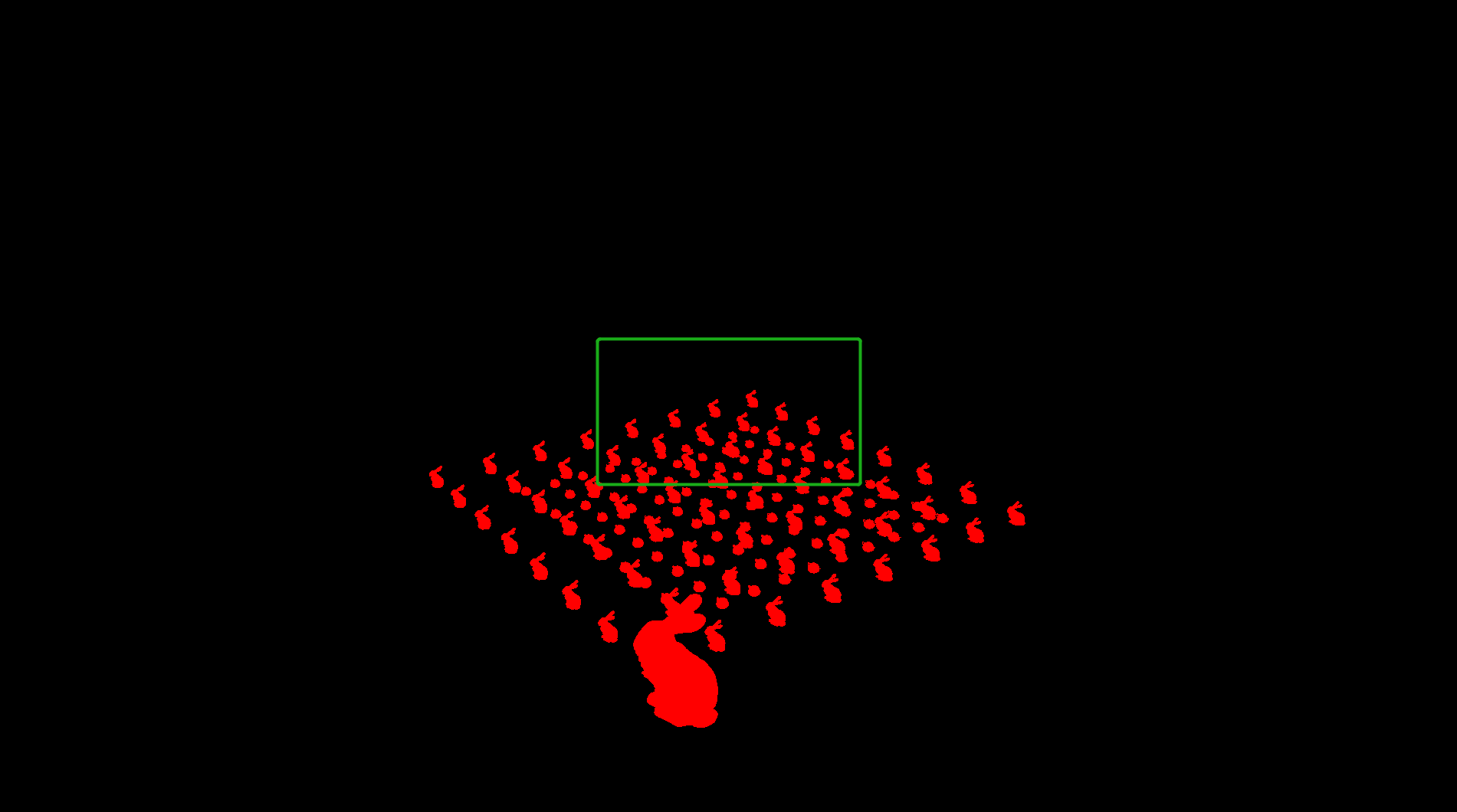
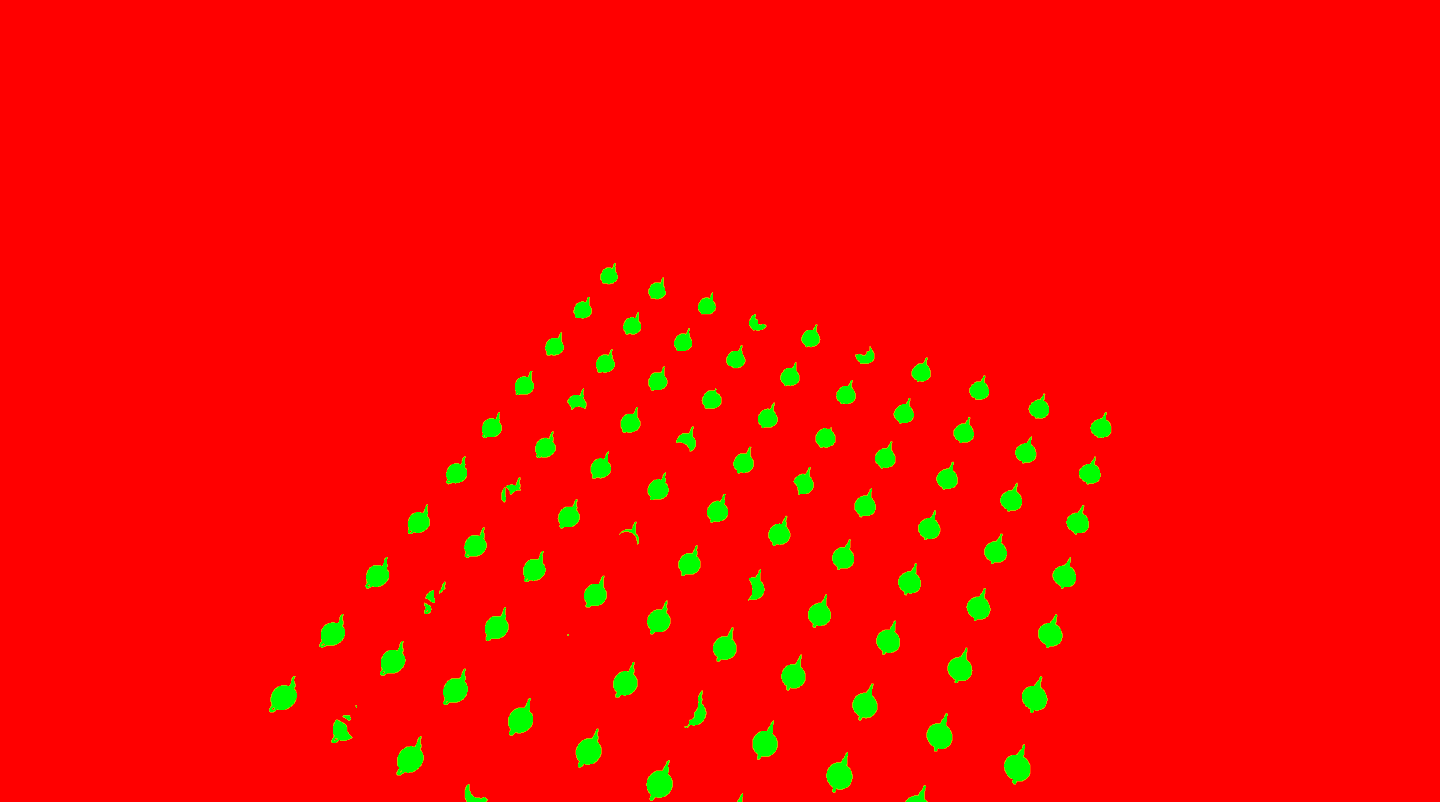
Below is a visualization of the software rasterization process. The green area is rasterized by the software compute shader.

Hardware Rasterization Part:
Software Rasterization Part:
Visualize Visibility Buffer:
BasePass or GBuffer Pass

With the visibility buffer, we can finally render the scene. First, SimNanite transfers the material index to the depth buffer, which will be used in the next pass’s depth test operation.

1
2
3
4
5
6
7
float ps_main(in float2 tex: TexCoord0): SV_Depth
{
uint2 load_pos = tex * rendertarget_size;
uint material_index = mat_id_buffer.Load(int3(load_pos.xy, 0));
float depth = float(material_index) / 1024.0;
return depth;
}

Then we draw a full screen quad for each material. The depth of this quad equals to material index.

1
2
3
4
5
6
7
8
9
10
void vs_main(
in uint VertID : SV_VertexID,
out float2 Tex : TexCoord0,
out float4 Pos : SV_Position)
{
float depth = float(material_index) / 1024.0;

Tex = float2(uint2(VertID, VertID << 1) & 2);
Pos = float4(lerp(float2(-1, 1), float2(1, -1), Tex), depth, 1);
};

Unreal’s Nanite dipatches an additional material classify pass to split the screen into tiles. Then Unreal uses indirect draw to draw the tiles generated in the previous pass, which reduces quad overdraw. In SimNanite, we remove the classify pass and draw the screen quad directly. For each material quad, we only render pixels that pass the material index depth test. Below are two material quad depth test figures. The first one is bunny material and the second one is teapot material.
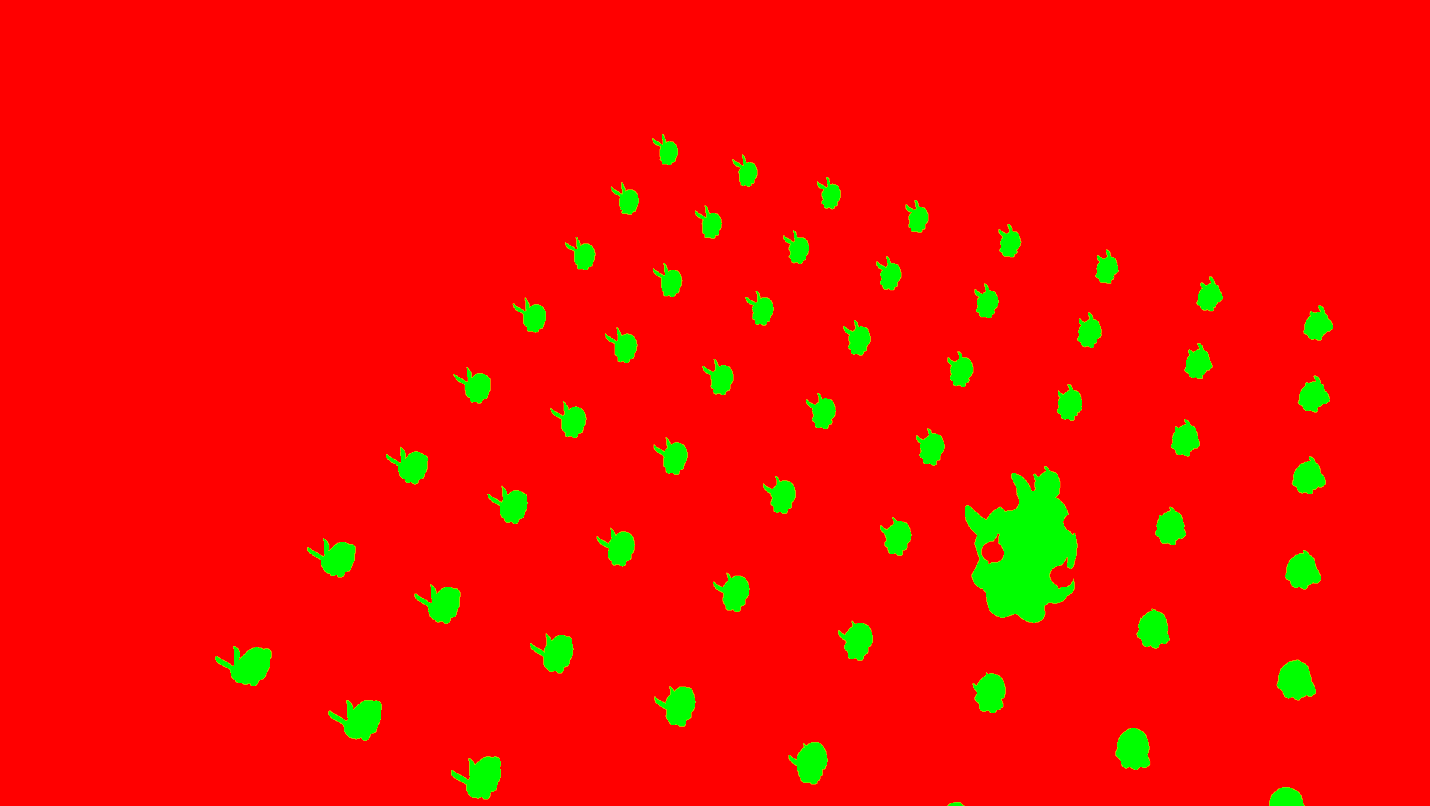
For each pixel, SimNanite fetches the cluster index and triangle index from the visibility buffer. Then, we calculate the barycentric coordinates based on the vertex position buffer. Finally, SimNanite calculates the vertex attributes, such as pixel UV and pixel normal by barycentric coordnates. The render the material with these attributes.

1
2
3
4
5
6
7
8
9
10
11
12
13
14
15
16
17
18
19
20
21
22
23
24
25
26
27
float4 ps_main(in float2 tex: TexCoord0): SV_Target0
{
uint2 load_pos = tex * rendertarget_size;
uint depth_buffer = in_depth_buffer.Load(int3(load_pos.xy,0));
float4 output_color = float4(0, 0, 0, 0);
if(depth_buffer != 0)
{
uint visibility_value = in_vis_buffer.Load(int3(load_pos.xy,0));
uint cluster_index = visibility_value >> 16;
uint triangle_index = visibility_value & 0x0000FFFFu;

// calculate vertex attributes
// ......

float3 barycentric = BarycentricCoordinate(float2(load_pos.x, rendertarget_size.y - load_pos.y), screen_pos_a.xy, screen_pos_b.xy, screen_pos_c.xy);
float z = 1 / (barycentric.x / position_a.w + barycentric.y / position_b.w + barycentric.z / position_c.w);
barycentric = barycentric / float3(position_a.w, position_b.w, position_c.w) * z;

float2 vertex_uv_a = asfloat(global_vertex_uv_buffer.Load2((start_vertex_location + indices.x) * 2 * 4 /* 2 * sizeof(float)*/));
float2 vertex_uv_b = asfloat(global_vertex_uv_buffer.Load2((start_vertex_location + indices.y) * 2 * 4 /* 2 * sizeof(float)*/));
float2 vertex_uv_c = asfloat(global_vertex_uv_buffer.Load2((start_vertex_location + indices.z) * 2 * 4 /* 2 * sizeof(float)*/));

float2 pix_uv = vertex_uv_a * barycentric.x + vertex_uv_b * barycentric.y + vertex_uv_c * barycentric.z;
float4 baseColor = baseColorTexture.Sample(baseColorSampler, pix_uv);
output_color = float4(baseColor.xyz, 1.0);
}
}

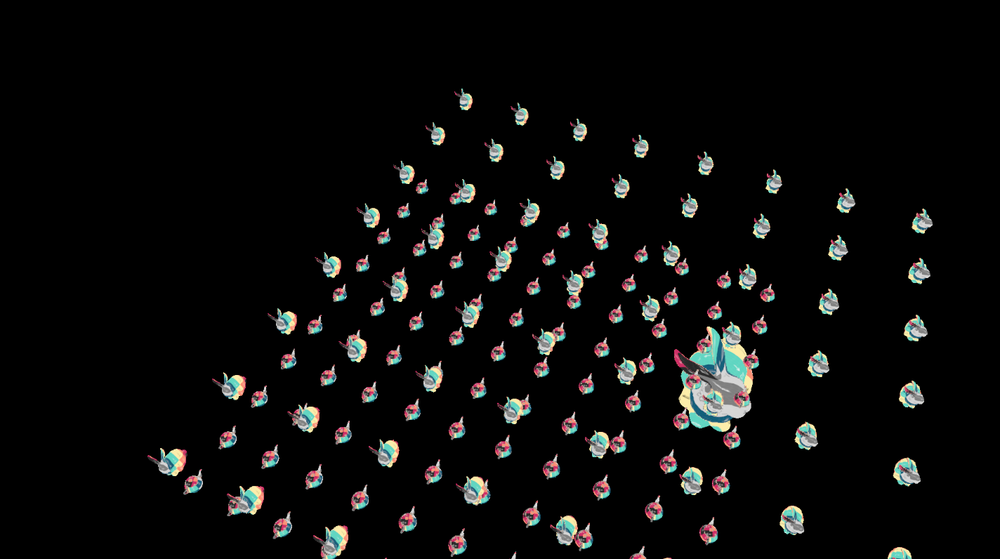
Bellow is the SimNanite final result:
simplified nanite code


Simplified Nanite In MiniEngine
http://example.com/2024/05/08/Simplified-Nanite-Virtualized-Geometry-In-MiniEngine/
Author
Shawn Tang
Posted on
May 8, 2024
Licensed under