Bindless Vulkan Ray Tracing In Cry Engine
Acceleration Structure Construction
Both DXR and Vulkan RayTracing use bounding volume hierarchies (BVH) as acceleration structure, which is also commonly used for offline ray tracing. BVH is an object partition data structure. It has more advantages than space partition (BSP-Tree,Octree,etc). One advantage of BVH is that the scene can be rebuilt easily for dynamic objects: just recompute the leaf node based on the current geometry. Additionally, the two-level acceleration structure employed in the current raytracing API can optimize rigid body animation further: only update the transform matrix without the expensive bottom-level acceleration structure update. Another advantage of BVH is that the maximum size used is known, as the number of leaves is limited
Two-Level Acceleration Structure
Vulkan uses a two-level acceleration structure to accelerate scene transversal and ray intersections. The bottom-level acceleration structure (BLAS) contains a set of geometries. In the Vulkan API, we can set two types of geometries: triangles or procedural. The former type contains a set of triangles, that is, actual vertex data and index data. Additionally, the BLAS with triangle geometry type contains AABB to encapsulate the geometry after it has been built. For the later geometry type, we should specify AABBs and the associated intersection function such as the ray-sphere test function. In practice, we prefer using triangle geometry, since both triangles and AABBs are hardware accelerated, but the procedural type involves additional user defined intersection functions in a shader, which is slower
The top-level acceleration structure (TLAS) consists of instances that reference the BLAS. And each instance contains a transform. We can only update the instance transform of TLAS for rigid-body animation
Top-level Acceleration Structure Construction
The Trade-Offs of Acceleration Structure Building
The driver is responsible for scheduling construction tasks after requesting the acceleration structure building. And the highly parallel work (calculate AABB, sort, etc) can accelerated by GPU. In addition, AS management (build/updata) can be moved to an async compute queue, which could completely hide the cost in many cases. AS management is essentialy software-based work, which allows the driver to optimize its construction algorithm continuously.
Vulkan exposed three build options to AS management:
For the PREFER_FAST_TRACE bit, the driver should choose the algorithm with better runtime transversal efficiency.
For the PREFER_FAST_BUILD bit, the driver should choose the algorithm with a faster construction rate.
For the default option, driver should choose a compromise solution with a balance between trace and build speed.
Generally, we employ PREFER_FAST_BUILD for BLAS, as well as PREFER_FAST_TRACE for TLAS.
Ray tracing has more geometries in GPU memory than traditional rasterization methods. Vulkan has provided additional options for compacting the acceleration structure. Generally, we only compact BLAS, since it has more geometry data than TLAS
What is the algorithm implemented in the driver behind the AS build options? There are three algorithms corresponding to PREFER_FAST_TRACE, PREFER_FAST_BUILD and the default option.
The first algorithm is called LBVH (Linear BVH). It uses linear ordering derived from spatial Morton codes to build hierarchies extremely quickly and with high parallel scalability.
LBVH is a simple split method and can’t guarantee the BVH build quality. SAH is a more commonly used algorithm. It’s a heuristic algorithm. It splits the scene meshes based on surface area. However, SAH needs to iterate all scene meshes during construction and take a lot of time during BVH construction.
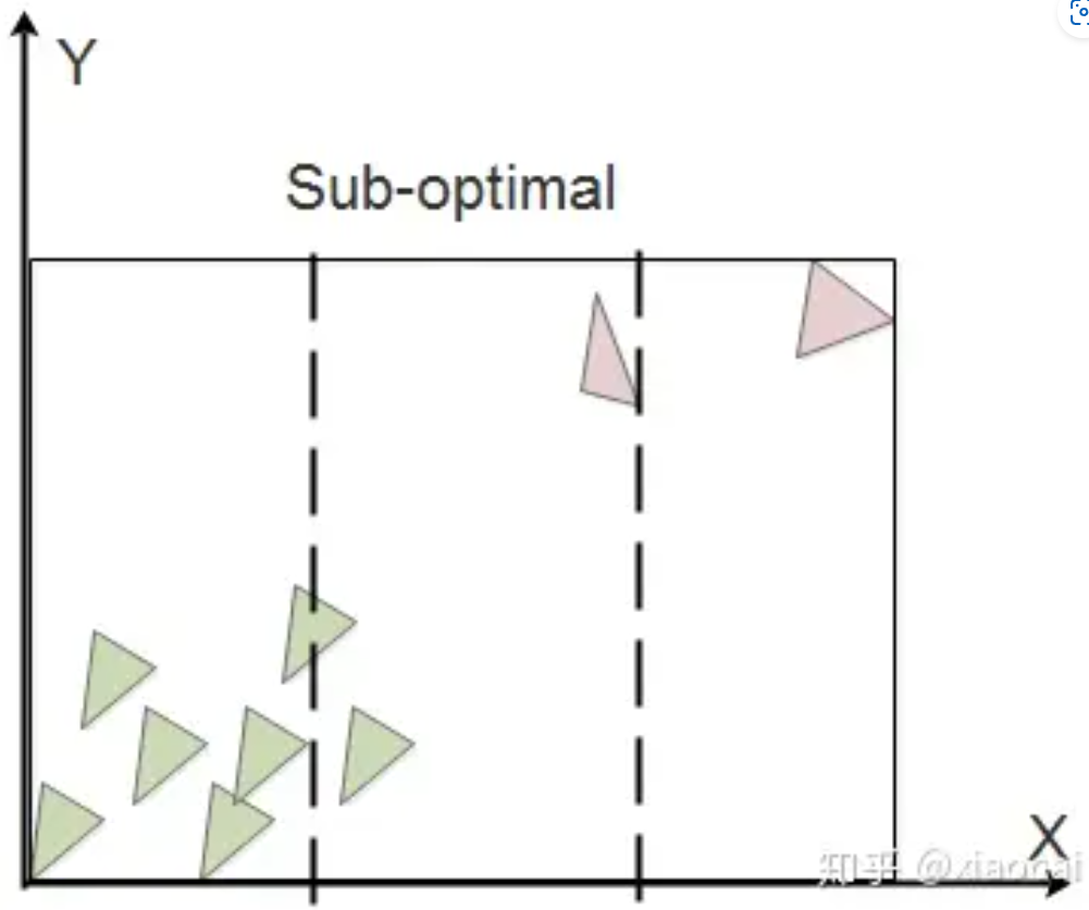
Binning-SAH is an optimized version of the SAH algorithm. The idea is to divide the node bounding box equally in a certain dimension K (such as 32), and then take the (K-1) equal points as the segmentation boundary (divide the triangles on both sides into two child nodes) to calculate (K-1) costs, and take the segment with the smallest cost. When splitting BVH nodes in complex scenarios, K is much smaller than N. Of course, the final partition might just be a suboptimal solution.
When there are unevenly sized triangles in the scene, the bounding boxes of the two child nodes after Binning SAH segmentation may overlap. This causes it to cost across both child nodes.
Spatial-split SAH is an algorithm to further improve the quality of binning SAH by eliminating the overlap problem, the idea being to allow the same triangle to enter two child nodes. For each node, Binning SAH is first used to find the optimal segmentation. If there is no overlap of bounding boxes between the two child nodes separated by Binning SAH, then the segmentation ends.
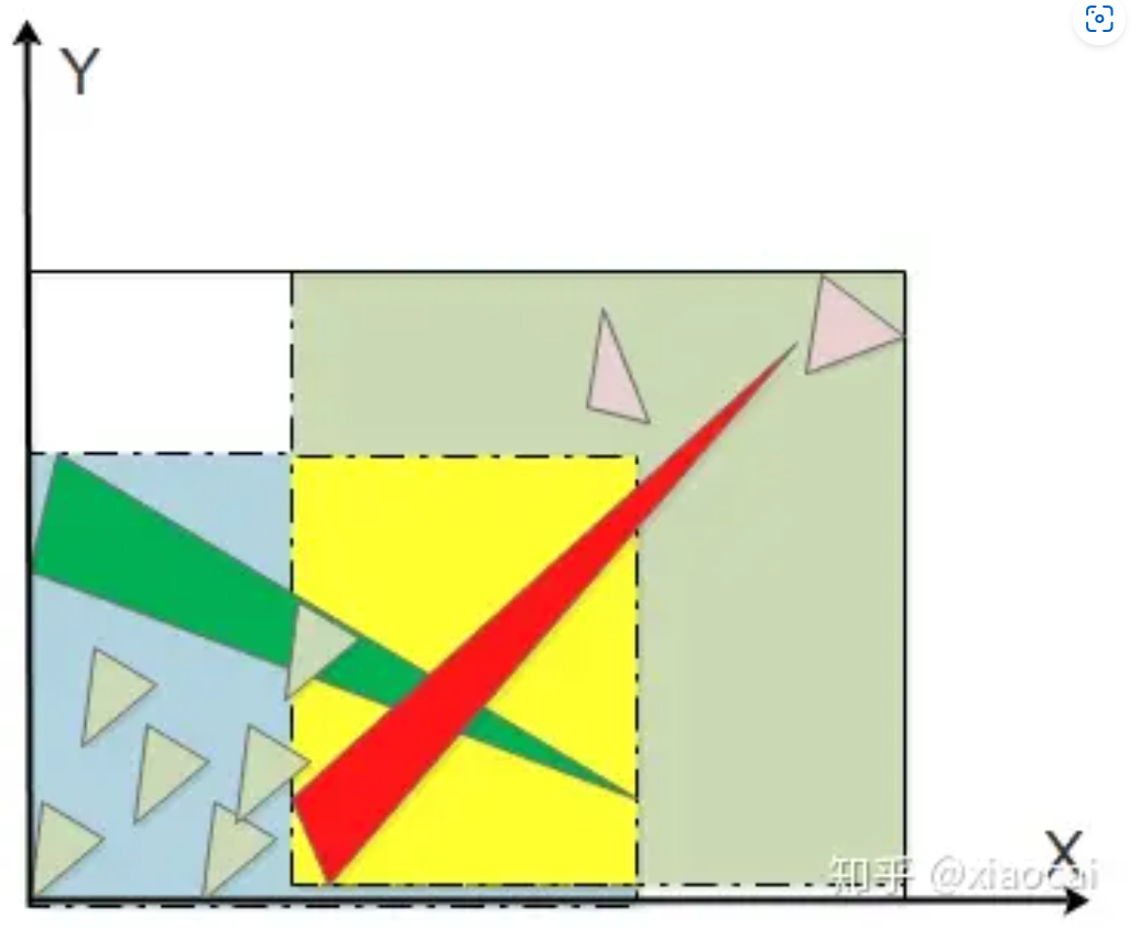
Otherwise, perform spatial-split, and the splitting step is as follows: split the node bounding box into K equal parts in a certain dimension. At (K-1) dividing points, any triangle is divided into the left node as long as some of the bounding box is on the left side of the dividing point. The right node as long as some is on the right side of the dividing point. Calculate the above (K-1) costs and take the partition with the smallest cost. If the cost is smaller than that of Binning SAH, then the Spatial-Split result is adopted.
AMD TLAS Rebraid
In AMD’s implementation, if the TLAS is built without the AllowUpdate flag, AMD GPURT will perform rebraid to improve the TLAS construction quality.
From AMD GPURT source code:
1 | |
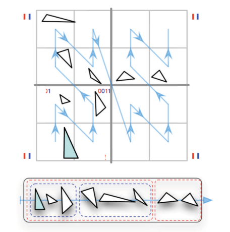
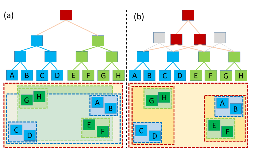
two objects (green and blue), each with their own BVH; with their topologies (top), and their spatial extents (bottom). As the objects spatially overlap and the top-level BVH (brown) has to treat them as monolithic entities a significant BVH node overlap in the spatial domain occurs, leading to low traversal performance. (b) Our method allows the top-level BVH to look into the object BVHs, and to “open up” object nodes where appropriate. This allows the top-level BVH to create new top-level nodes (brown) that address individual subtrees in the object BVHs, resulting in improved BVH quality
——from Improved Two-Level BVHs using Partial Re-Braiding
The core idea of rebraid is to:
1.start with object BVHs in the same way a traditional twolevel BVH would;
2.find a suitable “cut” through each object’s BVH such that the resulting set of BVH subtrees has low(er) overlap;
3.build a top-level BVH over those resulting subtrees.
Bottom-level Acceleration Structure Construction
Bottom-level acceleration structure construction is divided into three steps: construct the create information, create the acceleration structure and build the acceleration structure.
Construct the create information
In order to create an acceleration structure, we must obtain the size information of the acceleration structure by calling vkGetAccelerationStructureBuildSizesKHR, and then create the acceleration structure buffer with the calculated size. Next, call vkCreateAccelerationStructureKHR with the structure creation information, and store the result in accelerationStructureHandle. It is also necessary to obtain the device address of accelerationStructureHandle. This parameter is required in the next TLAS construction.
It should be noted that a new flag (USAGE_ACCELERATION_STRUCTURE) should be added to the creation of the acceleration structure buffer. It corresponds to XXX_STRUCTURE_BUILD_INPUT_READ_ONLY_BIT_KHR in my implementation, which indicates this buffer is suitable for use as a read-only input to an acceleration structure build.
1 | |
One of the advantages of BVH over space partitioning is that the structure size is known. Once the required data (vertex/index buffer, format, stride, etc) is ready, we can query the size of bottom-level acceleration structure information. The shape and type of the acceleration structure to be created is described in the VkAccelerationStructureBuildGeometryInfoKHR structure. This is the same structure that will later be used for the actual build, but the acceleration structure parameters and geometry data pointers do not need to be fully populated at this point (although they can be), just the acceleration structure type, and the geometry types, counts, and maximum sizes. These sizes are valid for any sufficiently similar acceleration structure.
1 | |
GetBottomLevelAccelerationStructureBuildInfo is a shared function between creating and building BLAS, which is the same as VkAccelerationStructureBuildGeometryInfoKHR. From this function, we can obtain the size for Create BLAS and the build information for Build BLAS.
Build BLAS
We construct the acceleration structure in batch mode by gathering all of the BLAS of each geometry and composing them into an array.
1 | |
In acceleration structure building, scratch buffers are required, but they are not used in ray tracing because acceleration structure buffers require more information, such as AABBs. These extra data are generated in VKCMDBuildAccelerationStructuresKHR. Therefore, the scratch buffer keeps temporary data, which can be released after building.Each BLAS in a batch can share a single scratch buffer, whose size is the total size of all the BLAS.
1 | |
Lastly, obtain the acceleration structure building geometry information, specify the scratch buffer device address, and build the acceleration structure in batches.
1 | |
Ray Tracing Shader Cross Compile
Add vulkan ray tracing shader support for cry engine.
Add Token
Cry Engine will initialize all shaders in the ‘mfInitShadersList’ function during Engine initialization. We need to add the tokens related to the ray tracing that are not supported by the Cry Engine parser. In Cry Engine, the token is parsed in the ‘m_Bin.GetBinShader->SaveBinShader’ function. To invoke this breakpoint, you need to delete the shader cache located in user\shaders\cache\vulkan. The core of this function is the following three steps:
1 | |
The NextToken function parses the tokens that exist in the g_KeyTokens table. The NewUserToken function inserts the unknown token into the token table. The value of these unknown tokens is generated by CRC.
Following are the tokens used in the vulkan ray tracing shader:
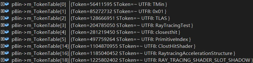
RaytracingAccelerationStructure: used for acceleration structure.[shader("raygeneration")]: used for shader type determination.
Tokens related to shader techniques: Shader technique is unique to Cry Engine. It is similar to the PSO, which indicates the shaders and the render state (depth state, blend state, etc).
1 | |
Cry Engine only supports one shader entry for each shader type for each pass. For example, a pass may have two entries (camera close hit and shader close hit shader) for close hit shader type. We need to support multi-entry shader type.
1 | |
Parse
Cry Engine parses the dummy shader first and skips all tokens except those related to the “technique”. During this process, Cry Engine enumerates all the shaders in the public techniques.Following are the tokens used in the dummy shader parser:
1 | |
Parse’s core function is ParseObject, which consists mainly of two steps. The first step is GetNextToken, where the next token is obtained. In addition, the more important part of Parse is to parse code fragments, such as preprocessed fragments or function code fragments. It also stores the function name, which is used to find the shader name later when parsing tech. In after parsing the code fragment, can be in ParseObject parse all code snippets of all statements, the Token is divided into the Name/Assign/Value/Data/Annotations type, These sub-SParserFrame in turn form a large ParserFrame based on, for example, semicolons, meaning that a code fragment contains multiple parse fragments, a CF (Code Fragment) may be a function, and a PF (Parse Fragment) may be an assignment or declaration statement.
And then re-initialize. The mfLoadDefaultSystemShaders function loads shader: sLoadShader (" RayTracingTestShader "s shRayTracingTest); And through the RT_ParseShaderCShaderManBin::ParseBinFX parsed Tokens, such as texture, float, struct, can parse and load or create a shader.
When parsing technique, CE does not support ray tracing shader. We added support for ray tracing shader in the ParseBinFX_Technique_Pass_LoadShaders_RayTracing function:
1 | |
We added support for shader types with multi shader entry:
1 | |
The shader entries are split by the comma token:
1 | |
CE technique supports only one shader, while the ray tracing shader consists of a series of shader tables. We need to add the parse and loading functions of shader tables specifically. We specify that all shaders of the same class in raytracing are placed in an array by {}, and then begin parsing shader binding table by { token. At the same time, SShaderPass is extended to support multiple stores for each shader
1 | |
Stored in an array after the CHWShader is parsed and created:
1 | |
Cross Compile
The next step is to create the shader (while creating the PSO), first get the shader from technique, and then check whether the shader is active based on the shader information. If it is not in the active state (CHWShader_D3D::mfActivate), mfCompileHLSL is called to trigger shader compilation. For debugging purposes, We’ve turned off asynchronous shader compiling for CE: CV_r_shadersasynccompiling
Ray tracing shader target is different from common shaders:
These shaders are functions compiled into a library, with target model lib_6_3, and identified by an attribute [shader(“shadertype”)] on the shader function
Set target to lib 6_3:
1 | |
What’s more, the DXC version of CE is older, and we need to upgrade it to the new version. In addition, you need to upgrade the version of spirv cross, otherwise shader reflection process will crash.
In addition, we need to revamp the reflection part of CE-spirv to support spirv’s reflection. Once we have the compiled data we need to create vulkan raytracing shader in mfUploadHW function.
1 | |
The above is the input of the hlsl shader after parsing. After compiling by DXC, we get the SPV result. We went through the spirv-cross to convert it to GLSL, and found that a conversion error occurred. After mapping, register t0 and u0 in HLSL have the same binding point:
1 | |
Here’s why the problem occurs:
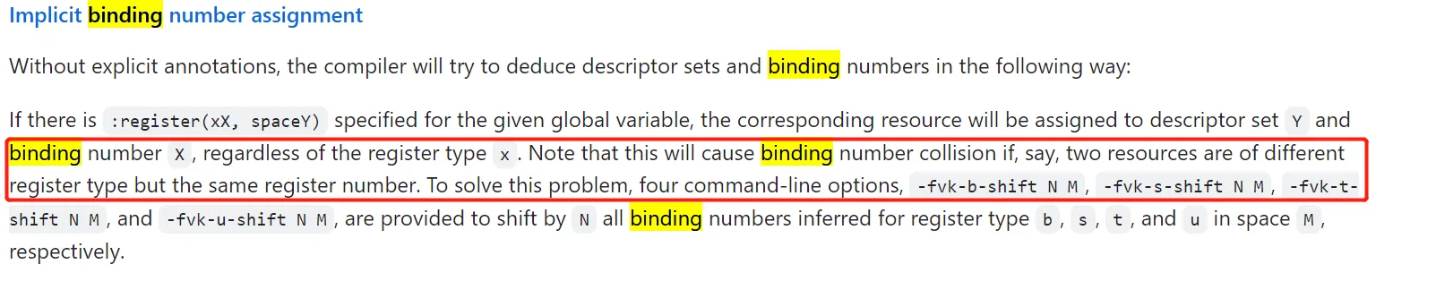
We solved the problem with [this blog]:
1 | |
It also needs to tweak the parse section of the code to skip [[vk::xxx]]
1 | |
Ray Tracing Pipeline
Cry Engine has three render passes: CComputeRenderPass, CPrimitiveRenderPass and CSceneRenderPass. We added a fourth render pass: ‘CrayTracingRenderPass’.
Compile RenderPass
When the PSO or other resources are dirty, Cry Engine rebuilds the resource in the Compile function. We create the PSO and shader binding table in the Compile function.
Resource Set
In the cry engine, the slot information is specified in the resource set step. For example, SetTexture with slot 2 corresponds to t2 in HLSL.
1 | |
SResourceBindPoint stores slot index, slot type and shader stages. These data are stored in uint8 format and packed into a uint32 variable thar will be used in state cache. SResourceBinding stores the resource and its view.
1 | |
When the resource layout is dirty, the layout needs to be rebuilt.
1 | |
Cry engine stores layout information into the cache through mfInsertNewCombination and decodes it during engine initialization. We extended ‘mfInitShadersCache’ and GetEncodedResourceLayoutSize in order to support ray tracing layout encoding.
During the engine initializes the layout, the cry engine decodes the binding information of the descriptor set through EncodeDescriptorSet. It includes the binding type and binding stage. This is used to map the DX binding to the Vulkan binding in the latter shader compiling process. We extended GetShaderStageFlags to support ray tracing. Cry engine uses the 6 bits of the uint8 to store the shader stage, which is not enough for ray tracing shader. We extended it to uint32 format to support RayGen/Miss/Hit shader stages.
1 | |
We need to pass in this hash in the shader compiling function GetRayTracingShaderInstanceInfo so that we can look up the layout later.
Add acceleration descriptor and descriptor pool support:
1 | |
1 | |
PSO Creation
New structures related to PSO creation:
1.CDeviceRayTracingPSODesc: Contains construction information.
2.CDeviceRayTracingPSO: Stores ray tracing PSO.
3.m_RayTracingPsoCache: Pipeline state cache.
Obtain and process the shader from the shader cache during PSO creation. It contains the following steps:
1.Get entry function name
1 | |
2.Get the Vulkan shader module and create a shader stage. All stages are stored in a std::vector of VkPipelineShaderStageCreateInfo objects. At this step, indices within this vector will be used as unique identifiers for the shaders.
1 | |
3.Create the shader group. Shader groups specify the shader stage index. Ray generation and miss shaders are called general shaders. In this case the type is VK_RAY_TRACING_SHADER_GROUP_TYPE_GENERAL_KHR, and only the generalShader member of the structure is filled
1 | |
Shader Binding Table
A shader binding table is a resource which establishes the relationship between the ray tracing pipeline and the acceleration structures that were built for the ray tracing pipeline. It indicates the shaders that operate on each geometry in an acceleration structure. In addition, it contains the resources accessed by each shader, including indices of textures, buffer device addresses, and constants. The application allocates and manages shader binding tables as VkBuffer objects
Each entry in the shader binding table consists of shaderGroupHandleSize bytes of data, either as queried by vkGetRayTracingShaderGroupHandlesKHR to refer to those specified shaders, or all zeros to refer to a zero shader group.
1 | |
The SBT is a collection of up to four arrays containing the handles of the shader groups used in the ray tracing pipeline, one array for each of the ray generation, miss, hit and callable (not used here) shader groups
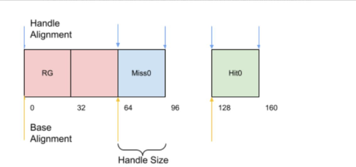
We will ensure that all starting groups start with an address aligned to shaderGroupBaseAlignment and that each entry in the group is aligned to shaderGroupHandleAlignment bytes. All group entries are aligned with shaderGroupHandleAlignment.
1 | |
In the next section, we store the device address of each shader group.
1 | |
The shader binding tables to use in a ray tracing pipeline are passed to the vkCmdTraceRaysNV, vkCmdTraceRaysKHR, or vkCmdTraceRaysIndirectKHR commands. Shader binding tables are read-only in shaders that are executing on the ray tracing pipeline.
1 | |
Bindless Ray Tracing
The limited nature of the binding slots meant that programs could typically only bind the exact set of resources that would be accessed by a particular shader program, which would often have to be done before every draw or dispatch. The CPU-driven nature of binding demanded that a shader’s required resources had to be statically known after compilation, which naturally led to inherent restrictions on the complexity of a shader program.
As ray tracing on the GPU started to gain traction, the classic binding model reached its breaking point. Ray tracing tends to be an inherently global process: one shader program might launch rays that could potentially interact with every material in the scene. This is largely incompatible with the notion of having the CPU bind a fxed set of resources prior to dispatch.
Fortunately, newer GPUs and APIs no longer suffer from the same limitations. Bindless techniques effectively provide shader programs with full global access to the full set of textures and buffers that are present on the GPU. Instead of requiring the CPU to bind a view for each individual resource, shaders can instead access an individual resource using a simple 32-bit index that can be freely embedded in user-defned data structures.
—— From Ray Tracing Gems:USING BINDLESS RESOURCES WITH DIRECTX RAYTRACING
Create a descriptor pool to store the descriptors. The size of the bindless descriptor pool is as large as possible to ensure that we can store all the descriptors used in ray training. When creating the Descriptor Pool, we need to add the flag VK_DESCRIPTOR_POOL_CREATE_UPDATE_AFTER_BIND_BIT_EXT to ensure descriptor sets allocated from this pool can include bindings with the VK_DESCRIPTOR_BINDING_UPDATE_AFTER_BIND_BIT bit set
1 | |
Create the Descriptor Set Layout with at least the flags VK_DESCRIPTOR_BINDING_PARTIALLY_BOUND_BIT_EXT and VK_DESCRIPTOR_BINDING_UPDATE_AFTER_BIND_BIT_EXT.
Descriptor binding flag VK_DESCRIPTOR_BINDING_UPDATE_AFTER_BIND_BIT: This flag indicates that if we update descriptor after it is bound (i.e using vkBindDescriptorSets), the command submission will use the most recently updated version of the descriptor set and most importantly, the update will NOT invalidate the command buffer.
Descriptor binding flag VK_DESCRIPTOR_BINDING_PARTIALLY_BOUND_BIT: This flag indicates that descriptor set does not need to have valid descriptors in them as long as the invalid descriptors are not accessed during shader execution.
1 | |
Then, create the actual descriptor set from the bindless pool:
1 | |
If we want to use a buffer as a bindless resource, we need to obtain the bindless index from the free list array managed by ourselves. We also need to update the descriptors in the global descriptor pool.
1 | |
Bind the bindless descriptor set during ray tracing dispatch if we use bindless descriptor set.
1 | |
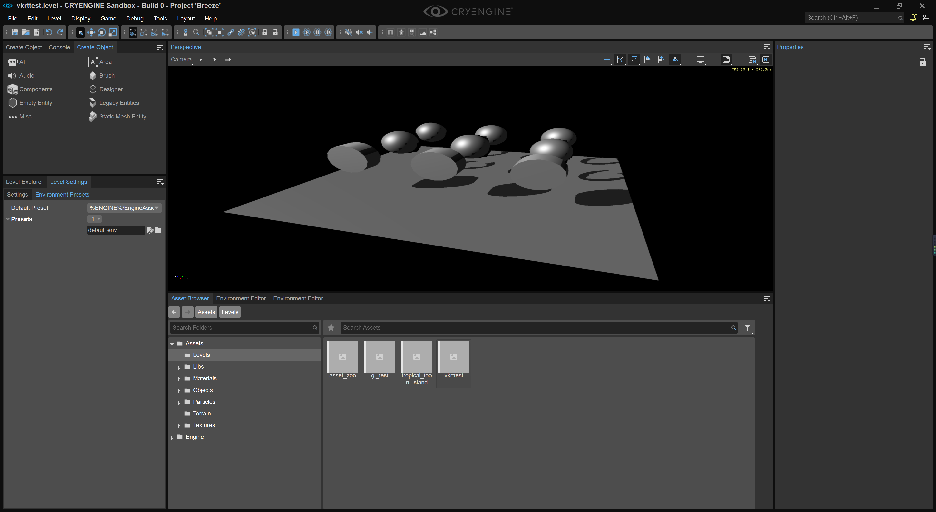
result in cry engine: