MP_IPDOM And GPU Hardware Simulation
Overview
GPUs use SIMT (single-instruction, multiple-thread) to execute the same instructions in several threads. GPGPU-Sim uses SIMT stack to simulate SIMT. SIMT stack is a single-path stack execution model. Its serialization of divergent control flow paths reduces thread-level parallelism. MP IPDOM enables multi-path execution with support for an arbitrary number of divergence splits while maintaining reconvergence at the IPDOM.
We implemented the MP IPDOM in this project based on the original paper and this post using GPGPU-SIM. We added an additional structure, simt_reconvergence_table, to record the reconvergence items and modified the code to support parallel warp execution. The split warp in MP IPDOM could run parallel. Since the original scoreboard only recorded the register usage per-warp instead of per-split warp, we modified the scoreboard to track register usage in each split warp.
GPU Brach Divergence
Current graphics processing units (GPUs) enable nongraphics computing using a Single Instruction Multiple Threads (SIMT) execution model. The SIMT model is typically implemented using a single instruction sequencer to operate on a group of threads, called a warp by NVIDIA, in lockstep. This amortizes instruction fetch and decode cost improving efficiency. To implement the SIMT model a mechanism is required to allow threads to follow different control flow paths. Current GPUs employ mechanisms that serialize the execution of divergent paths. Typically,they ensure reconvergence occurs at or before the immediate postdominator (IPDOM) of the divergent branch
This serialization of divergent control flow paths reduces thread level parallelism (TLP), but this reduction can be mitigated if the concurrent execution of divergent paths is enabled.
MP IPDOM
SIMT stack is a single-path stack execution model. Its serialization of divergent control flow paths reduces thread-level parallelism. MP IPDOM enables multi-path execution with support for an arbitrary number of diverged splits while maintaining reconvergence at the IPDOM.
MP IPDOM observes that the SIMT stack items could be divided into two parts based on their role: execution and reconvergence waiting.The core idea is that those items for execution could be executed parallelly, which means the warp splits generated after divergence could be executed individually in a separate control path.
To achieve this we replace the SIMT reconvergence stack structure with two tables.
The warp Split Table (ST) records the state of warp splits executing in parallel basic blocks (i.e., blocks that do not dominate each other), which can therefore be scheduled concurrently.
Please note that we reused the simt structure as the split table. The only difference is the R-Index, which would be described later.
1 | |
The Reconvergence Table (RT) records reconvergence points for the splits.
1 | |
The ST and RT tables work cooperatively to ensure splits executing parallel basic blocks will reconverge at IPDOM points.
The Basic Workflow of MP IPDOM
We will use a simple CUDA program to describe this part. The control flow graph is similar to the example shown in the original paper.
1 | |
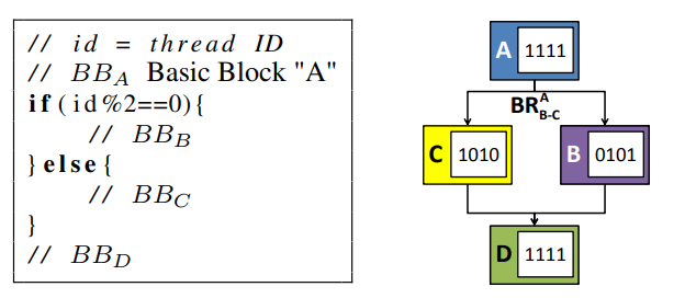
Here is the PC of each code block, which helps you understand the following parts.
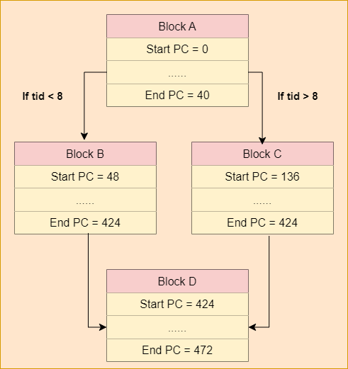
Please note that we should disable NVCC compile optimization when we compile the cuda program.
1 | |
Below shows the operation of the MP IPDOM illustrating changes to the ST and RT tables.
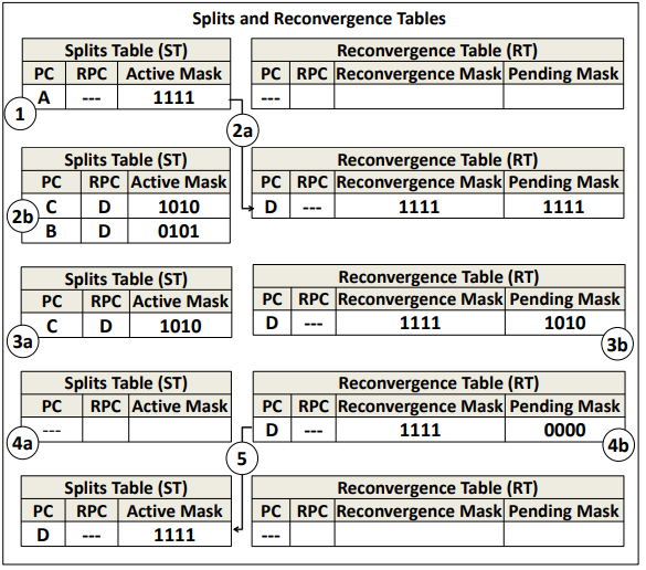
Step1:
The warp begins executing at block A. Since there is no divergence, there is only a single entry in the ST, and the RT is empty.
Step2A:
Then, the warp is scheduled on the pipeline until it reaches the end of block A. After the warp executes branch on cycle 2, warp A1111 diverges into two splits B0101 and C1010. Then, the A1111 entry is moved from the ST to the RT.
If divergence occurs and the new recovergence PC is not equal to the last recovergence PC, add a new recovergence item to the recovergence table.
1 | |
The log shows that divergence occurs at cycle 21. The first divergent path contains threads from 8 to 31 in the warp, corresponding to FFFFFF00. Another divergent path contains threads from 0 to 7 in the warp, corresponding to 000000FF.

Step2B(1):
with PC field set to the RPC (recovergence PC) of branch (i.e., D).
1 | |
In our example, the start PCs of branches B and C are 48 and 136 respectively. They are recovergence at PC 424, which is shown below.
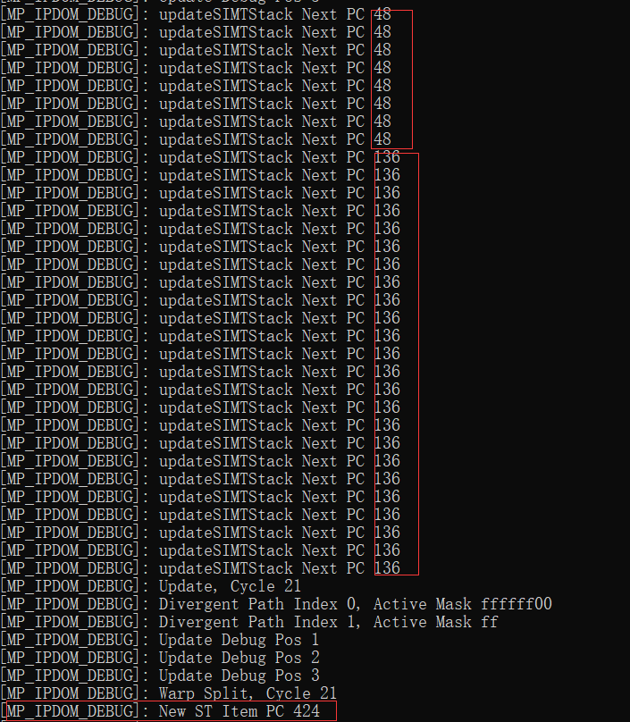
Step2B(2):
The RPC can be determined at compile time and either conveyed using an additional instruction before the branch or encoded as part of the branch itself (current GPUs typically include additional instructions to manipulate the stack of active masks).
The reconvergence PC (RPC) of the new RT (reconvergence table) item is equal to the RPC of the last ST (split table) item. In this example, it equals -1. We will describe it more deeply in the next section that introduces nested MP IPDOM.
1 | |
Step2B(3):
The Reconvergence Mask entry is set to the same value of the active mask of the diverged warp split before the branch.
1 | |
Before the branches B and C, there is no divergence, which means the active mask is equal to FFFFFFFF.

Step2B(4):
The Pending Mask entry is used to represent threads that have not yet reached the reconvergence point. Hence, it is also initially set to the same value as the active mask
1 | |

Step2B(4):
At the same time, two new entries are inserted into the ST; one for each side of the branch 2b . The active mask in each entry represents threads that execute the corresponding side of the branch.
We should pop out the SIMT stack structure, which contains the reconvergence item, and move it to the reconvergence table since we reuse the SIMT stack structure as a split table.
1 | |
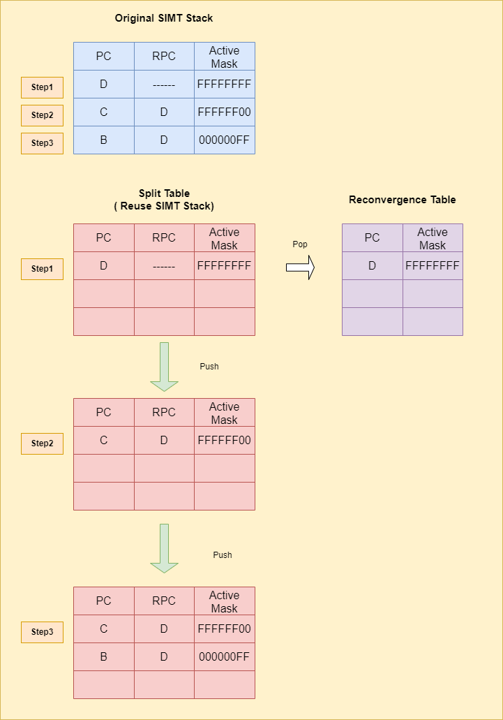
Then add two new items to the split table.
1 | |
The new items in the split table should record the R-Index which is the index of its corresponding reconvergence item in the reconvergence table.
1 | |
Step3A:
On the clock cycle 3, warp splits B0101 and C1010 are eligible to be scheduled on the pipeline independently. We assume that the scheduler interleaves the available warp splits. Warp splits B0101 and C1010 hide each others’ latency leaving no idle cycles (cycles 3-5). On cycle 6, warp split B0101 reaches the reconvergence point (D) first.
1 | |
We have arrived at the reconvergence PC shown in Step2B (1).

Step3B:
Therefore, its entry in the ST table is invalidated, and its active mask is subtracted from the pending active mask of the corresponding entry in the RT table
Retrieve the corresponding R-Index (reconvergence table index) first.
1 | |

1 | |
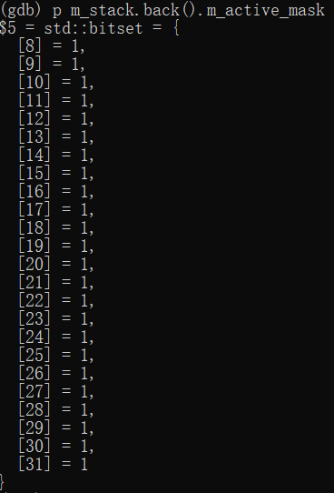
The active mask of the entry in the split table is FFFFFF00 in our example.
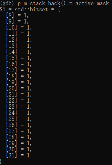
Since this warp split is invalidated, the corresponding mask of the reconvergence item in the RT is subtracted.
Step4A:
Later, on cycle 7, warp split C1010 reaches reconvergence point (D). Thus, its entry in the ST table is also invalidated. and its active mask is subtracted from the pending active mask of the corresponding entry in the RT table.
Another warp split whose active mask is 000000FF arrives at reconvergence point.

We subtract its active mask, similary.
Upon each update to the pending active mask in the RT table, the Pending Mask is checked if it is all zeros, which is true in this case.
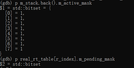
Step5:
The entry is then moved from the RT table to the ST table

Move the reconvergence item in the RT to the split table and reset the active threads.
Finally, the reconverged warp D1111 executes basic block D on cycles 7 and 8.
Nested Divergence
Figure 6 illustrates how MP IPDOM handles nested branches. It shows the state of the ST and RT tables after each step of executing the control flow graph in the left part of the figure. In our explanation of this example, we assume a particular sequence of events that results from one possible scheduling order. However, Multi-Path IPDOM does not require a specific scheduling order.

The workflow of nested divergence is similar to the last example. There are two steps we should notice: Step 3->4 and Step 6->7.
Step 3->4:
At this point MP IPDOM exposes parallelism in three parallel control flow paths, which means branches B, D and E could execute parallelly. We will detail it in the later section.
Step 6 -> 7:
The active mask of RT item is used when moving item from RT to ST. Besides, it plays an important role in nested branches, which help the item transform between the RT to the ST. The F-G item plays two roles in this example: parallel execution (in split table) and serial execution (in reconvergence table).
Parallel Control Flow Path
In this section we will discuss the implementation details of parallel branch.
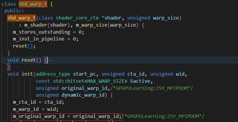
After Step2D described above, we split the warp into two warps, in orther words, generating another warp. Please note that we will not assign new threads to this warp, since the role of this new warp is to carry the needed information and it is actually executed in the original thread.
1 | |
The original warp ID in the above code snippet is initialized when launching the SIMT stack, helping us find the original thread that performs the computation.
split warp workflow:
1.First, find an idle warp in the shader core
1 | |
2.Initialize the idle warp and assign the original warp ID.
1 | |
3.launch new warp
1 | |
When updating the SIMT stack during issue warp, we should use the original warp ID to retrieve the correct thread for getting the next PC.
1 | |
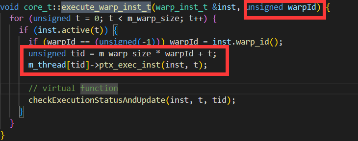
As described before, we use the original thread to execute the instructions.
1 | |
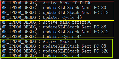
Below is the result of MP IPDOM. The next PC in cycle 43 is 80 for warp 1 and 312 for warp 2. After execution, the next PC in cycle 44 is 88 for warp 1 and 320 for warp 2, which means they are executed parallel.
Scoreboard Logic
We use the example in part: The Basic Workflow of MP IPDOM to introduce the scoreboard workflow during execution, which is different from the original paper.
Our Example:
1 | |
Before discussing the modification to the scoreboard, we introduce the original scoreboard first.
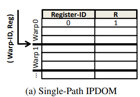
Current GPUs use a per-warp scoreboard to track data dependencies. A form of set-associative look-up table is employed, where sets are indexed using warp IDs and entries within each set contain a destination register ID of an instruction in flight for a given warp.
1 | |
When a new instruction is decoded, its source and destination register IDs are compared against the scoreboard entries of its warp.
Here is the compare function in GPGPU-SIM. For each incoming instruction, the scoreboard get all the registers used and compare it with the corresponding register table.
1 | |
The decoded instruction of a warp is not scheduled for issue until the scoreboard indicates no WAW or RAW hazards exist. The scoreboard detects WAW and RAW hazards by tracking which registers will be written to by an instruction that has issued but not yet written its results back to the register file.
Scheduler units can only issue warps for the current instruction when there are no WAW or RAW hazards, i.e. when the function checkCollision returns false.
1 | |
The scoreboard will reserve registers used for the current warp since it passed the register collision test.
1 | |
When the reserved registers are released at the write back stage, they can be used by other instructions.
1 | |
The Multi-Path IPDOM supports multiple number of concurrent warp splits running through parallel control flow paths. Hence, it is essential for the scoreboard logic to correctly handle dependencies for all warp splits and across divergence and reconvergence points. It is also desirable for the scoreboard to avoid declaring a dependency exists when a read in one warp split follows a write to the same register but from another warp split.
The MP IPDOM supports multiple control flow path running parallel, which means we should records the register usage for every thread.
We modified the scoreboard table. Each warp has a map storing the register usage for every thread (active_mask_t).
1 | |
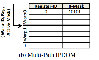
checkCollision Modification:
Compared to the original implementation, MP_IPDOM passes an additional variable, the active mask of the current warp (msk). We iterate over all registers used in the current instruction, comparing the msk with the reserved_msk, which indicates whether the register is used by the current thread. If any registers collide, return true, which means collision occurs and the current instruction won’t be issued.
1 | |
reserveRegister Modification:
If the instruction passes the collision test, we should reserve registers for those threads that execute the current instruction during issue warp.
1 | |
releaseRegister Modification:
The releaseRegister modification is similar to reserveRegister: we release those registers at the write back stage.
1 | |