Stochastic Progressive Photon Mapping In Alpha7XRenderer
Introduction
I have written a post explaining SPPM and implemented a DXR version of photon mapping (Screen Space Photon Mapping) based on the ray tracing gems. The purpose of this post is to describe how SPPM is implemented in my tiny offline renderer using embree, Alpha7x that references PBRT. Before describing SPPM, we should first introduce some related algorithms: PM (basic photon mapping) and PPM (Progressive Photon Mapping).
Basic Photon Mapping
Path tracing is impossible for the LS(S|D)*S path. A simple LSDS path is shown below, which includes a point light, a pinhole camera, and a diffuse surface behind a sheet of glass.
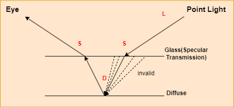
The glass is specular transmission. In this post, specular is absolute specular, in other words, its roughness is zero, which means only one input lighting direction contributes to the final light. And transmission means there is no contribution from reflection in our example.
There is only one light path that contributes to the given camera ray in this example, which is nearly impossible to be found. In path tracing, a ray is traced from a camera and first hits a glass surface. Since the glass is specular transmission, the direct lighting contribution is zero and the ray refracts to the other side of the glass. After refraction, the ray hits the diffuse material and generate a random ray to trace the input light. As we described before, only one direction is valid for the generated rays. The probability of selecting this particular ray is nearly zero.
The basic photon mapping algorithm solves this problem by resusing the nearyby photons, which introduces bias. Although it is a bias method, it could be consistent by increasing the sample number, which will be described later.
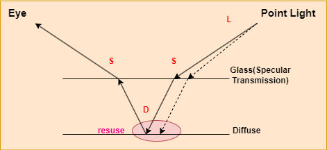
The basic photon mapping is a two pass algorithm:
1.Photons are first traced from the light source. Photon interactions are recorded on the surfaces of the scene and then organized in a spatial data structure (generally a KD-tree) for use at rendering time.
2.A second pass follows paths starting from the camera; at each path vertex, nearby photons are used to estimate indirect illumination.
Considering that it is similar to SPPM, which will be discussed in more detail later, we will not delve into its details at this time. There is a limitation to the basic photon mapping method, in that the amount of memory available to store photons is limited, thus limiting the amount of photons that can be traced. In the path tracing algorithm, we could trace infinite rays, which means as the number of iterations increases, the rendering quality improves, but basic photon mapping rendering could not be improved once the memory limit was reached.
Progressive Photon Mapping
The basic photon mapping algorithm stores the light path shot from the light source. As we discussed above, the light photons shot from the light are limited due to the memory limitation. Rather than storing the light path, progressive photon mapping addresses this issue by storing the camera path that traced from the camera.
This algorithm is also a two-pass method, but it differs from the basic PM algorithm in that it is inverse of it:
1.PPM traces the paths starting from the camera at first. Each pixel stores a representation of all of the non-specular path vertices found when generating paths that started in its extent. These vertices are named as visible points.
2.Traces photons from the light sources; at each photon-surface intersection, the photon contributes to the reflected radiance estimate for nearby visible points.
Please note that we only record the first diffuse hit point on the surface. When trace the camera starting from the camera, we calculate the direct lighting along this path.
In PPM the light transport equation could be decomposed into two separate integrals over direct and indirect incident radiance at each visible points.
It will not be discussed further the terms emitted and direct lighting, which is similar to path tracing. The basic idea behind camera path search is to locate a visible point that can reuse nearby photons by preserving the photons traced from the light source on the surface of the visible point. Since diffuse surfaces are ideal for storing photons, we trace the path from the camera until it hits the diffuse surface.
In the basic photon mapping method, the photons are static after they are traced from the light source. The camera visible points are dynamic that change during iteration.
In progressive photon mapping, the camera visible points remain static after being traced by the camera. Photons are dynamic, as they increase during iteration.
The basic photon mapping algorithm is limited by its static part, photon number. Similar, the progressive photon mapping algorithm is also limited by its static part, camera visible points. For high resolution images or images that require many samples per pixel to resolve motion blur or depth of field, memory can still be a limitation.
The stochastic progressive photon mapping algorithm addresses these issues by converting camera visible points and photons into dynamic variables that could be changed during iteration.
Stochastic Progressive Photon Mapping
Here is the main workflow of stochastic progressive photon mapping:
1 | |
For each iteration,
1.Trace rays from the camera, record the visible points on the first hit diffuse surface and calculated the direct lighting along the camera path found.
2.Construct the SPPM grid based on the visible points found in step 1.
3.Trace photons from the camera and calculate their contribution to nearby visible points along the light path.
4.Update visible points parameters, such as radius.
Before each iteration begins, the photons and visible point positions generated previously are discarded, which means the camera paths and the light paths are dynamic during each iteration.
Trace Camera Path
The procedure for tracing the camera visible points is similar to path tracing. The visible points traced from the camera record its position at the first diffuse intersected surface and the output direction and the bsdf when it hits the diffuse surface.
1 | |
The basic workflow is as follows:
1.Generate a ray that is traced from the camera.
1 | |
2.Intersect the ray with the scene. Alpha7x uses embree to perform ray-scene intersection.
1 | |
3.Sample and accumulate the direct lighting.
1 | |
4.If the intersection surface is diffused, stop tracing and record the visible point.
1 | |
5.Otherwise, generate a new ray randomly and update the path throughput.
1 | |
6.Russian roulette.
Direct Lighting Result:
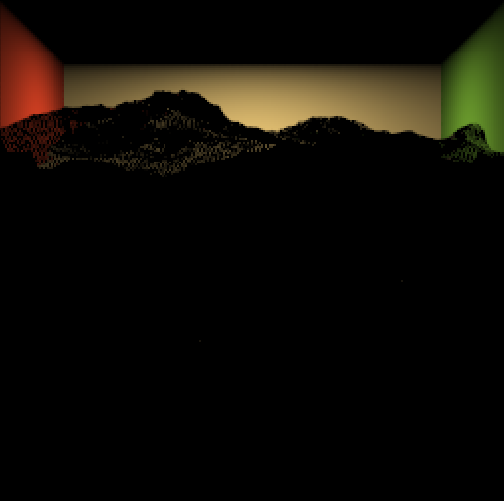
SPPM Grid Construction
The contribution of a photon to nearby visible points should be calculated when it hits the scene, so we need an efficient data structure (for example, K-D tree) for finding nearby visible points. In alpha7x, we use hash grid to accelerate the nearby visible points search.
In each grid, there is a list of visible points that overlap the current grid.
1 | |
As visible points are located on the mesh surface, grids not located near the mesh surface do not have visible points. Therefore, most grids are sparsely filled. Our SPPM uses a hash function to transform the 3D grid index into a 1D array index, so we store the visible points in an array of visible points liststd::vector<SGridVisiblePointsList*> grids;.
1 | |
The grid bound is defined by the union of the visible points’ positions in the scene, and the grid resolution is determined by calculating the maximum search radius of the visible points.
1 | |
Then, iterate over all of the visible points generated in the last step and add them to the corresponding grids.
1 | |
There will be no contributions to the grid for camera pixels that do not find any visible points (for example, when the ray leaves the scene), which is path throughput equal to zero ().
1 | |
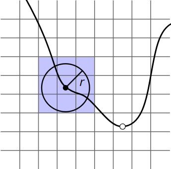
Given a visible point (filled circle) with search radius , the visible point is added to the linked list in all grid cells that the bounding box of the sphere of radius overlaps. Given a photon incident on a surface in the scene (open circle), we only need to check the visible points in the voxel the photon is in to find the ones that it may contribute to.
1 | |
Trace Photons
Next, trace photons from the light source. Here is the workflow.
1.Select a light from the scene randomly.
2.Sample an outgoing ray from the light. Based on the following equation, we can determine the initial path throughput:
The probability of sampling this particular light is measured by , while the probability of selecting this position on the light is measured by , and the probability of selecting this outgoing ray by .
1 | |
3.Trace the photon though the scene.
1 | |
4.Calculate the photon’s contribution to the near visible points when it hits the surface. Since the first intersection with the scene represents direct lighting which is already accounted for in the first step, we calculate the photon’s contribution from the second intersection.
1 | |
A visible point records radiant flux using phi. The radiant flux of nearby visible points is accumulated when photons hit the surface.
The radiance is thw power emmited, reflected, transmitted or recieved by a surface, per solid angle, per projected unit area, which means:
Its discrete representation is shown below, where is the path throughput.

1 | |
Based on the above equation, every visible point in this grid whose distance to the photon is less than the radius should accumulate photon contributions. It should be noted that reusing nearby photons is incorrect mathematically, except when the radius is zero. This operation introduces the bias. The total number of contributing photons in this pass is stored in M.
5.Update the path throughput.
1 | |
6.Russian roulette.
Update Visible Points Parameters
Radius Reduction
The PPM algorithm generates photon mapping progressively. Then, it estimates the density of the photon maps and combines them together:
There is a problem with the radius being fixed in this case. As we mentioned above, the SPPM is a biased but consistent method when its gathering radius is towards zero. So it is critical to decrease the gathering radius during iteration.
After the first iteration, the photon density is shown in the following formula:
And the photon density after the second iteration is:
If we trace enough photons, the density of photons in the first and second iterations is the same, which means that:
and
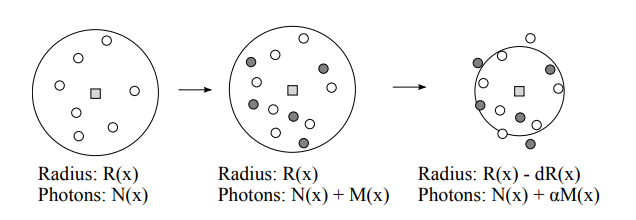
Each hit point in the ray tracing pass is stored in a global data structure with an associated radius and accumulated photon power. After each photon tracing pass we find the new photons within the radius of each hit point, and we reduce the radius based on the newly added photons. The progressive radiance estimate ensures that the final value at each hit point will converge to the correct radiance value. For simplicity, we use a parameter = (0, 1) to control the fraction of photons to keep after every iteration.
Therefore,
Then,
In PBRT, the is 2/3:
1 | |
Flux Correction
The unnormalized total flux received for visible points is . As we have generated a new radius for the next iteration, the value should be corrected, since the radius is decreasing and some photons are outside the updated radius.
One method for finding those photons would be to keep a list of all photons within the disc and remove those that are not within the reduced radius disc. However, this method is not practical as it would require too much memory for the photon lists.
For simplicity, we assume:
1 | |
Radiance Evaluation
After each photon tracing pass we can evaluate the radiance at the hit points. Recall that the quantities stored include the current radius and the current intercepted flux multiplied by the BRDF. The evaluated radiance is multiplied by the pixel weight and added to the pixel associated with the hit point. To evaluate the radiance we further need to know the total number of emitted photons in order to normalize τ (x, ~ω). The radiance is evaluated as follows

Result
Below is the SPPM result. Each pixel traces 200 samples and during each iteration traces 256 * 256 photons from the camera.
